Common Operations
This section introduces the following common operations:
- Conduct a simulation test on ports.
- Modify system parameters.
- Back up system parameters.
- Check system logs.
- Save and recover coordinates.
- Check machining statistics.
- Compensate the tool.
- Compensate screw error.
- Execute instant calibration.
Conduct a Simulation Test on Ports
This operation is used to conduct a simulation test on input ports and output ports to simulate hardware signal. And it helps to judge whether a port has output depending on the status of the indicator light.
Indicator status of input ports and output ports for simulation is as follows:
- Input ports:
 means having a signal;
  means no signal.
 - Output ports:
 means having a signal;
  means no signal.
Indicator status is also connected with port polarity. See Adjust I/O Port Polarity for details.
Before conducting a simulation test, ensure that Read-only attribute for the select port is No. You can press F5 in Port interface to change the read-only attribute.
To conduct a simulation test on ports, do the following:
To enter into Port interface, press
 → A:
→ A: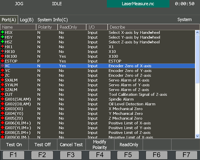
To make the indicator light before the selected port shift between
 (test on) and
  (test off), press F1 or F2.
To exit the simulation test on all ports, press F3.
Modify System Parameters
This operation is used to tell how to change system parameters in Machine Param interface.
According to user' roles and permission, system parameters can be divided into:
- User's parameters: default parameters
- Manufacturer's parameters: manufacturer password is required.
- Developer's parameters: developer password is required.
To modify system parameters, do the following:
To enter into Machine Param interface, press
 → A.
→ A.To find the target parameters, press ↑ / ↓.
Press Enter, and input a value according to your need.
Optional: Do one of the following according to valid time of these modified parameters:
- Now: skip this step.
- Restart: restart the system to make modification effective.
- Reload: reload the program file to make modification effective.
After system parameters have been modified well, back up system parameters. See Back up System Parameters for details.
Back up System Parameters
This operation is used to prepare a second copy of the parameter settings to restore the settings in the future or for other CNC integrated systems, so as to save the trouble of setting them again.
Before backing up system parameters, ensure that system parameters have been set well. For how to set system parameters, see Modify System Parameters for details.
To back up system parameters, do the following:
To enter into Param Backup interface, press
→ B: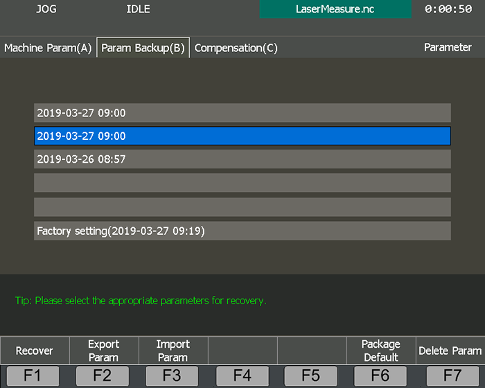
To back up current parameter settings to factory setting, press F6.
To export parameter settings to a USB flash disk, press F2.
After restarting the system, the exported time shows in Param Backup interface.
In Param Backup interface, you can also do the following:
To import a parameter file in a USB flash disk into the system, press F3.
To recover parameter setting to a desired backup time, press ↑ / ↓ to select the desired time, and press F1.
To delete backup parameters, press F7. The system deletes backup time and backup parameter settings.
Check System Logs
This operation is used to view important operations and system events since this time start-up and in history for troubleshooting.
System logs include the following types:
- System startup and shutdown
- Start and stop of automatic machining
- Change of workpiece offsets
- System alarms
- Prompts about machining
- Other system information
To check system logs, do the following:
To enter into Log interface, press
→ B: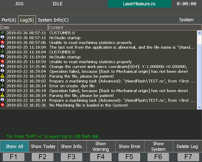
Check different types of system logs:
- To check all logs, press F1. It is pressed by default.
- To check today's logs, press F2.
- To check logs about running status, press F3. Logs with icon
 show in Log interface.
 - To check warning logs, press F4. Logs with icon
 show in Log interface.
 - To check error logs, press F5. Logs with icon
 show in Log interface.
 - To check system logs, press F6. Logs with icon
 show in Log interface.
You can also do the following in Log interface:
To delete all system logs, press F7.
Note: Please delete system logs regularly. Otherwise, too many log files will slow down the system.
To export system logs to a USB flash disk, press shift and L.
Save and Recover Coordinates
This operation is used to keep the workpiece offsets for later use and get back the previously saved workpiece offsets to save the trouble of repeatedly setting the workpiece offsets.
To save and recover coordinates, do the following:
To enter into Coor Backup interface, press
 → X:
→ X:
To save coordinates, do the following:
Press ↑ / ↓ to select the target line No.
Press F1. The system saves the workpiece offsets of the current program file into the target line No.
If the workpiece offset already exists in the target line No., the operation will overwrite it.
To recover coordinates, do the following:
To select the target line No, press ↑ / ↓.
Press F2, and choose whether to recover the workpiece offset of Z-axis:
- To recover the workpiece offsets of all axes, press Y in the two pop-up dialog boxes.
- To recover the workpiece offsets except Z-axis, press Y only in the first pop-up dialog box.
Check Machining Statistics
This operation is used to check the collection of machining information shown in numbers of both current program file and program files in history.
To check machining statistics, do the following:
To enter into Part Statistic interface, press
 → =:
→ =: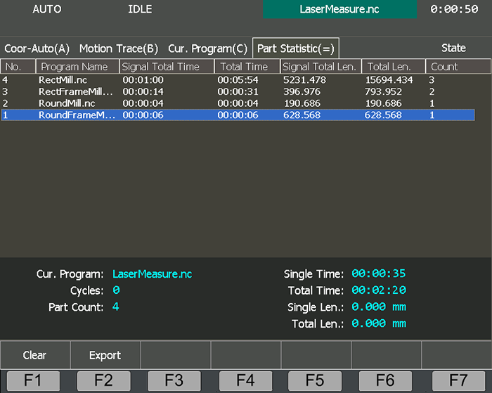
Check the following machining information:
Single Time : The time for each machining of the program file.
Total Time : The total time for current machining task.
Single Length : The length for the program file.
Total Length : The total length for current machining task.
Count : The total machining times of the program file.
When cycle machining is disabled, the single total time is equal to total time, and single total length is equal to total length.
See Execute Cycle Machining for cycle machining.
In Part Statistic interface, you can also do the following:
To clear all statistics, press F1.
To export all statistics to a USB flash disk, press F2.
The statistics will be saved as a TXT file.
Compensate the Tool
This operation is used to compute the corresponding coordinates of the tool center or the related point of the tool rest, according to the actual coordinate position of the tool rest or the cutting edge.
With this operation, you can directly input the new tool parameter values in the Compensation interface, if the tool nose radius is altered due to tool wear, tool sharpening or tool change. It saves trouble of modifying the programmed program file.
Before compensating the tool, do the following:
Set parameter Enable Cutter Compensation to Yes to enable tool compensation.
Set parameter Tool Compensation Type based on your own needs.
Measure and record the following values:
- Tool diameter
- Tool diameter wear
- Tool length
- Tool length wear
To compensate the tool, do the following:
To enter into Compensation interface, press
→ C: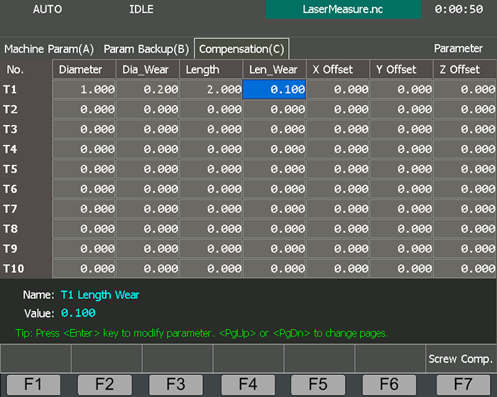
To select the target tool number, press ↑ / ↓.
Press ← / → to select the target input box, press Enter, and modify the value of the parameter according to the measured values.
Tool compensation can be achieved by calling related commands. See NcStudio Programming Manual for details.
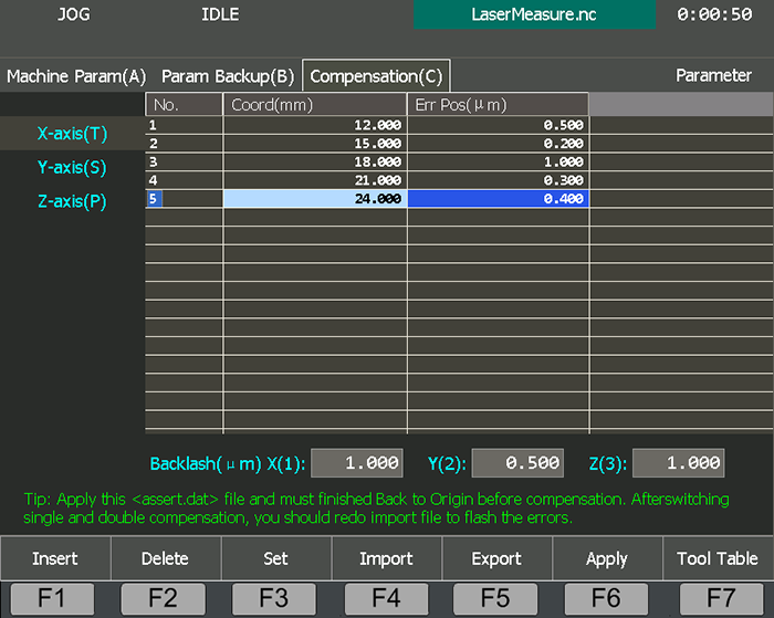
Compensate Screw Error
This operation is used to compensate screw pitch error and errors caused by backlash, to achieve high precision.
To compensate screw error, do the following:
To enter into Compensation interface, press
→ C.To enter into Screw Comp. page, press F7:
Do one of the following:
Compensate Screw Error by an External File
This operation is used to automatically compensate screw error based on the error data in the file, after the backward error and forward error of the corresponding nominal coordinate of each coordinate axis are listed into the screw error compensation file.
Before compensating screw error by an external file, do the following:
Write a compensation file for screw error, name it
axeserr.dat, and save it into the root directory of a USB flash disk.Inset the USB flash disk into host.
To compensate screw error by an external file, do the following:
Press F4 → F1. Import Compensation Data dialog box pops up.
Select the target compensation data.
Note: If the value of parameter Screw Error Comp is modified, you need to import the target compensation data again.
You can also export the imported compensation file to a USB flash disk for later use by pressing F7 →F5.
Compensate Screw Error by Related Parameter Settings
This operation is used to compensate screw error by setting compensation parameters about screw error in the software directly.
To compensate screw error by related parameters, do the following:
To select the axis needed to compensate, press T / S / P.
Do one of the following:
Press F3, and set the start position, interval and amount for compensation.
Press F1 to insert a blank line, and set the start position.
Note: It is not allowed to insert several blank lines at the same time.
To set unidirectional compensation, press ↑ / ↓ / ← / → to select the target input box of Err Pos, press Enter, and input a value according to the actual situation.
Optional: If backlash is needed, press 1, 2 or 3 to set backlash for each axis.
To save and validate the setting, press F6.
Execute Instant Calibration
This operation is used to automatically execute fixed calibration for several tools.
See Execute Fixed Calibration for details.
To execute instant calibration, do the following:
To enter into Auto mode, press
.To enter into OneKey Cali interface, press
→ =: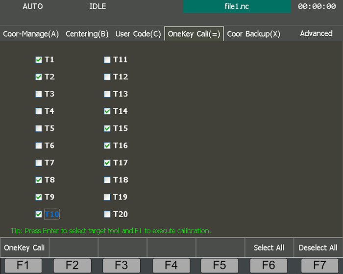
To select target tools, do the following:
- Press ↑ / ↓ → Enter.
- Press F6, and select all tools.
- Press F6, and remove all selected tools.
To start instant calibration, press F1.
The system automatically changes the tool and start to calibration.