Basic Commissioning
Through this section, you can quickly get familiar with the commissioning process about NK260/NK280/NK280B:
- Switch the system configuration.
- Adjust I/O port polarity.
- Set commissioning parameters.
- Check the axis direction.
- Return to the machine origin.
- Set speed parameters.
Switch the System Configuration
This operation is used to check if the default system configuration is what you need and change it according to the structure of the machine tool if not when the system is installed at the first time.
To switch the system configuration, do the following:
To enter into System Info interface, press
 → C.
→ C.Press F4, and enter the manufacturer password. Switch Config dialog box pops up:
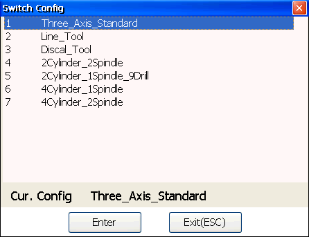
The current system configuration is shown in grey at the bottom of the dialog box.
Optional: If the current system configuration is not what you need, press ↑ / ↓ to move the cursor to the desired one, and press Enter.
Restart the software to validate the modification.
Adjust I/O Port Polarity
This operation is used to adjust polarities of input / output ports in the software in terms of the switch type, and clear alarms of I/O ports, so as to establish correct communication between the system and the drive:
- The polarity of normally closed switches should be N.
- The polarity of normally open switches should be P.
Except special customization, the polarities of output ports are N in general.
Before checking I/O ports, ensure the machine tool is connected well and powered on.
To adjust I/O port polarity, do the following:
To enter into Port interface, press
→ A.If the status of the following ports is different from the actual status of the machine tool, check the connection:
- ESTOP
- Servo Alarm
- Tool Calibration Signal of Z-axis
- Mechanical Zero
- Cycle Start
- Cycle Stop
If the connection is not correct, tighten the connection; if it is, proceed to the next step.
Press ↑ / ↓ to select the target port, enter the manufacturer password, and click Modify Polarity to convert its polarity.
Restart the software to validate the modification.
In Port interface, you can also execute other operations about port. See Conduct a Simulation Test on Ports for details.
Set Commissioning Parameters
This operation is used to set parameters for commissioning, to avoid damage to the machine tool during its movement.
According to the type of control systems, it can be divided into the following:
- Set commissioning parameters for bus control system. (Exclusive to NK280B)
- Set commissioning parameters for non-bus control system.
Set Commissioning Parameters for Bus Control System
Before setting commissioning parameters for bus control system, ensure the following:
- Parameter Control System Type is set to 1.
- The used terminal board is Lambda 5M.
To set commissioning parameters for bus control system, do the following:
To enter into Machine Param interface, press
 → A.
→ A.To check manufacturer's parameters, press F2, and input the manufacturer password.
Find and set the following parameters:
Drive Station Address : It should match with toggle switch setting of the driver station address. : Number of each drive station address should be unique, such as X-axis is set 1, Y-axis is set to 2, and Z-axis is set to 3... : 0 is invalid.
Encoder Digit : The encoder digit of a servo motor.
Lead Screw Pitch : It refers to the axial distance between the corresponding points of two adjacent teeth on the threads.
TravelLimits-Positive / TravelLimits-Negative : The movement range of each axis in X-axis, Y-axis and Z-axis direction. : The system will carry out soft limit in terms of this range in order to protect the machine tool.
Electronic Gear Ratio : It refers to the ratio that the servo enlarges or shrinks the received pulse frequency. : It consists of parameter Numerator of Electronic Gear Ratio and Denominator of Electronic Gear Ratio. : B represents its numerator, while A represents its denominator. : If it is greater than 1, the servo enlarges the received pulse frequency; if it is less than 1, the servo shrinks the received pulse frequency. : It setting should match with the value of drive parameter Electronic Gear Ratio. : It is 1:1 by default. :
 : F stands for encoder resolution; p stands for pulse equivalent; d stands for pitch; m/n stands for mechanical reducer ratio.
Set Commissioning Parameters for Non-bus Control System
For NK280B, before setting commissioning parameters for non-bus control system, ensure the following:
- Parameter Control System Type is set to 0.
- Parameter Encoder Type is set to 0.
To set commissioning parameters for non-bus control system, do the following:
To enter into Machine Param interface, press
→ A.To check manufacturer's parameters, press F2, and input manufacturer password.
Press F2, find and set the following axis parameters according to the actual situation:
Pulse Equivalent : It refers to the moving distance of screw or rotation degree of the rotary axis per pulse sent by the system, the minimum available distance controlled by the system as well. : Smaller value gets higher machining precision and surface quality; while larger value gets faster maximum feedrate.
TravelLimits-Positive / TravelLimits-Negative : The movement range of each axis in X-axis, Y-axis and Z-axis direction. : The system will carry out soft limit in terms of this range in order to protect the machine tool.
Press F4, find and set the following origin parameters according to the actual situation:
Motor Type : The motor type. : 1: Stepping motor. 2: Servo motor.
REF Switch Positioning Direction : In REF switch positioning phase, the moving direction of each axis during returning to the machine origin.
REF Switch Positioning Speed : In REF switch positioning phase, the feedrate of each axis during returning to the machine origin.
REF Encoder Positioning Speed : In encoder positioning phase, the feedrate of {AXIS}-axis during returning to the machine origin.
Lead Screw Pitch : It refers to the axial distance between the corresponding points of two adjacent teeth on the threads.
Back Distance : After fine positioning stage of returning to the machine origin, the additional displacement of each axis. : +: Positive direction; -: Negative direction.
Coarse/Fine_Switches_Min_Dist : Used to see if coarse and fine switches are too close. : Valid range: [0, thread pitch/2].
Check the Axis Direction
This operation is used to ensure that the axis direction is the same with the direction stipulated by Right Hand Rule, to avoid damage to the machine tool due to incorrect direction.
Taking X-axis as an example, to check the axis direction, do the following:
Judge the positive direction of X-axis according to the Right Hand Rule.
To switch to Manual mode, press
 /
/  /
/  .
.Press 4 / 6 or control the handwheel to move X-axis, and observe its moving direction.
Optional: If the moving direction is opposite to the judged direction, modify the setting value of parameter Axis Direction(X) to the opposite value.
Return to the Machine Origin
According to the encoder type, this operation can be divided into:
Set Datum with an Absolute Encoder
This operation is used to return to the machine origin with an absolute encoder by directly setting datum when it is your first time to use the system. And it owns the following advantages compared to returning to the machine origin with an incremental encoder:
- No need to set returning orders for all axes in datum setting process.
- No need to set datum again after restarting the system, recovering from power interruption and E-stop because the system will automatically read the datum information.
Note: You need to set datum again when the absolute encoder is out of battery.
Before setting datum, ensure the following:
- Hardware devices have been well connected.
- The axis direction is correct. See Check the Axis Direction for details.
- Parameter Enable Encoder Feedback is set to Yes.
- Parameter Encoder Type is set to 1.
Taking X-axis as an example, to set datum with an absolute encoder, do the following:
To enter into BACKREF mode, press
 .
.To enter into Coor-Reference interface, press
 → A.
→ A.To enter into Datum Setting page, press F5.
Press 4 / 6, and move X-axis to a fixed position.
Press F1. The system automatically reads X-axis position and sets it as X-axis datum.
After setting datum successfully, the sign  appears in front of X-axis in coordinate display area.
Repeat the above steps, set datum for other axes, and restart the software to validate the setting.
After setting datum for all axes, to avoid datum loses after updating the software or during transporting machine tools, press F6 to export datum to a USB flash disk for later use.
Return to the Machine Origin with an Incremental Encoder
Origin of Machine Coordinate System (MCS), also called machine origin, and home, is a fixed point assigned by design, manufacturing and debugging before the machine tool leaves factory. This operation is used to return to the point.
This operation is required each time you restart the system.
Before returning to the machine origin with an incremental encoder, ensure the following:
- Hardware devices have been well connected.
- The axis direction is correct. See Check the Axis Direction for details.
To return to the machine origin with an incremental encoder, do the following:
To enter into BACKREF mode, press
.To enter into Coor-Reference mode, press
→ A.Do one of the following:
Press F7. Z-axis returns to the machine origin firstly, then other axes return.
Press F1 / F2 / F3. The specified axis returns to the machine origin.
For safety, it is suggested that Z-axis returns to the machine origin firstly.
After returning, the sign appears in front of related axes in coordinate display area.
Set Speed Parameters
This operation is used to set parameters about speed for commissioning to get a good machining effect.
To set speed parameters, do the following:
To enter into Machine Param interface, press
→ A.Press F2, and input the manufacturer password.
Press F1, find and set the following operation parameters:
JOG Jerk : Jerk under rapid-jog mode.
JOG Feedrate before Ref. : The default maximum feedrate in jog mode before returning to the machine origin.
Manual High : The speed under rapid-jog mode.
Manual Low : The default speed under jog mode.
Max Spindle Speed : The maximum rotational speed of spindle. : It should be consistent with the settings of inverter.
Handwheel Acceleration : Handwheel acceleration. : Smaller value gets smoother handwheel movements.
Press F3, find and set the following program parameters:
Feedrate : The default feedrate during machining.
Machining Acceleration : The maximum acceleration for machining.
Max Speed of Ref. Circle : The maximal allowable speed of reference circle with 10mm diameter.
Max Acceleration at Corners : The maximum acceleration at corners.
Machining Jerk : Machining Jerk. : It is only valid on GXX.
Maximum Axial Feedrate : The default maximum feedrate of each axis during machining
Maximum Axial Rapid Traverse Speed : The maximum speed of each axis during positioning.
Max Axial Speed : The maximum speed of each axis.
Max Axial Machining Acceleration : The maximum acceleration of each axis during machining.
Max Axial Rapid Traverse Acceleration : The maximum acceleration of each axis during positioning.
Max Axial Jerk : The maximum axial jerk.
Startup Speed : The initial also the minimum speed during machining.
Circular Processing Min Speed : The minimum speed during machining an arc.
Max Acceleration at Feed Override Change : When feed override changes, smaller max acceleration gets smoother movements.
Approaching F : During rapid positioning, the feedrate when the tool is approaching the workpiece.
Press F5, find and set the following parameters about tool change:
Rapid Traverse Speed in Tool Change : The rapid traverse speed during tool change.
Z-axis Speed in Tool Change : The default speed at upper and lower position of Z-axis during tool change.
Horizontal Speed when Tool In/Out Tool Mag. : The default speed of Z-axis moving into/out of tool magazine during tool change.