Machining Operations
Through this section, you can mainly know the following machining related operations:
- Execute selective machining.
- Generate a wizard file.
- Execute cycle machining.
- Execute array machining.
- Execute the program task.
- Simulate machining.
- Execute MDI.
- Guide machining by the handwheel.
Execute Selective Machining
This operation is used for an optional skip of the program file, so that you can freely select the machining range.
To execute selective machining, do the following:
To enter into AUTO mode, press
 .
.To open Start Line dialog box, do one of the following:
- Press
 → A → F2.
 - Press
 → C → F1.

- Press
To start machining according to the actual demand, select the start line:
- To start machining from the beginning of the program file, press T.
- To start machining from the set line, press S and manually input the start line.
To stop machining according to the actual demand, select the end line:
- To stop machining till the end of the program file, press P.
- To stop machining till the set line, press Q, and manually input the end line.
The system automatically starts machining from the set start line to the set end line.
Generate a Wizard File
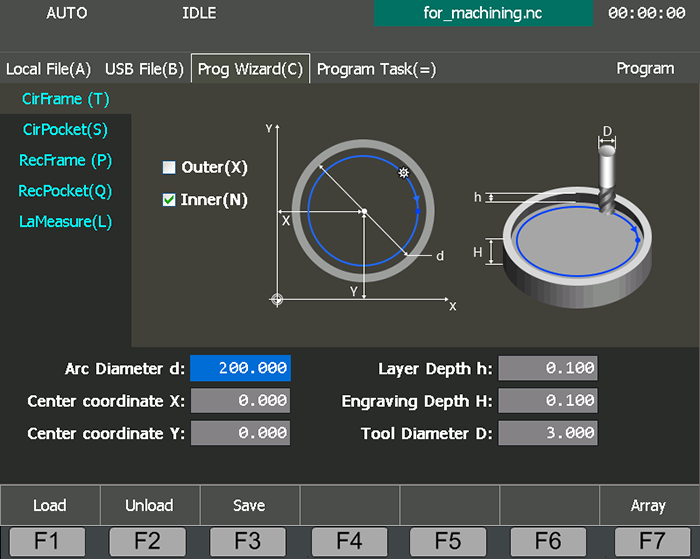
This operation is used to generate a wizard file by program wizard.
To generate a wizard file, do the following:
To enter into Prog Wizard interface, press
 → C:
→ C:
Select a kind of wizard:
- T: CirFrame
- S: CirPocket
- P: RecFrame
- Q: RecPocket
- L: LaMeasure
Set related parameters.
To generate a program file and save it, press F3.
To load the program file, press F1.
If you need to unload the file, press F2.
Execute Cycle Machining
This operation is used to complete all machining actions with a program file for batch machining, carving machining, etc.
Before executing cycle machining, do the following:
To execute cycle machining, do the following:
To enter into AUTO mode, press
 .
.To enter to Coor-Auto interface, press
 → A.
→ A.To set machining times of the current program file, set the value of parameter Prog Cycle Times.
Find Parameter Cycle Machining Interval, and set the interval between two machining tasks for cycle machining.
Note: After restating the software or reloading the program file, cycle times will be cleared and you need to set it again.
Execute Array Machining
This operation is used for batch machining of the currently loaded program file, so as to improve machining efficiency.
To execute array machining, do the following:
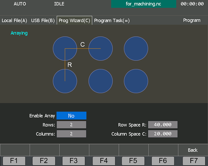
To enter into Arraying page, press
 → C → F7:
To enable array machining, move the cursor to the input box of Enable Array, press Enter, and press 1.
Press ↑ / ↓ / ← / → to move the cursor to the related input box, and set a value.
Rows : The number of rows for array machining.
Columns : The number of columns for array machining.
Row Space : The space between each row.
Column Space : The space between each column.
When machining starts, the system pops up a dialog box to confirm whether to enable array machining, and starts array machining after your confirmation.
Execute the Program Task
This operation is used to put several program files into a task by setting machining order, machining interval, used WCS and machining times for each program file.
Before executing the program task, ensure that there are several program files in the local or USB flash disk.
To execute the program task, do the following:
Create a Program Task
To create a new program task, do the following:
To enter into Program Task interface, press
 → =:
→ =:
To create a new program task, press F2 → F1. A program task named as
New Task + No.shows.Optional: To rename the program task, press F3.
To open the program task for later editing, press F6.
To enter into File List page, press F7 → F1.
Optional: To add program files in the USB flash disk into the program task, press F6.
It is default to add local program files.
Press ↑ / ↓ and F2 / F3 / F4 to select the target file, and press F1 to add it into the program task.
Press F7 to exit creating the program task.
Edit the Program Task
To edit the program task, do the following:
Press ↑ / ↓ / ← / → to select the target input box, press Enter and modify the following:
- Used WCS
- Machining interval
- Machining times
Press F3, press ↑ / ↓, and do one of the following:
To modify the machining order in the program task, press F1 / F2.
To remove the target program file from the program task, F3.
To save the modification, press F6.
Start the Program Task
To execute the program task, do the following:
To select a machining mode, do the following:
- To select One by One Mode, press N.
- To select Single Mode, press T.
Optional: To set cycle times for the program task, press S.
To load the program task, press F6. Names of the program task and the first program file in the task show above the display screen.
Optional: To set the first program file, press L.
To start machining the program task, press
 .
.
The system automatically does the following according to the set machining order:
Load the first program file, start to machine it, and unload it when machining ends.
Do one of the following:
In One by One Mode, load the second program file, and wait for the set interval, start to machine the program file, and unload it when machining ends, repeat these steps until all program files in the program task have been machined.
In Single Mode, load the second program file, and enter into Pause status.
It will not start to machine the second program file unless you press
 manually.
Simulate Machining
This operation is used to provide a fast but lifelike simulation machining environment to see the moving from of the machine tool in advance, so as to avoid damages to the machine tool due to programming mistakes.
During simulating machining, no actual machining occurs.
To simulate machining, do the following:
To enter into AUTO mode, press
 .
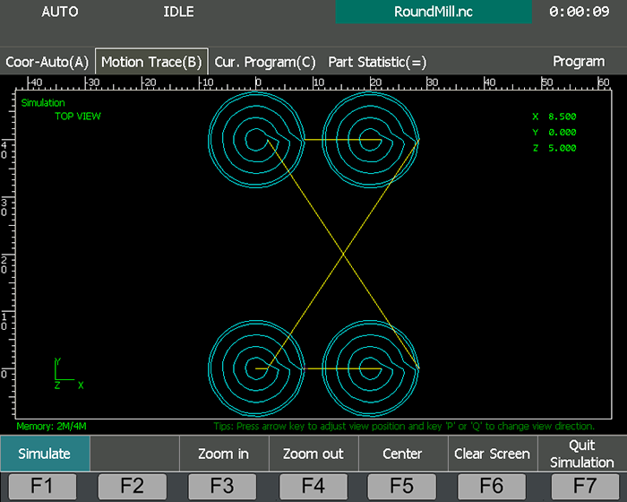
.To enter into Motion Trace interface, press
 → B:
→ B:
To start simulating machining, press F1.
The moving trace of the machine tool shows in Motion Trace interface.
During simulating machining, you can also do the following:
- Press F3 / F4 / F5 to zoom in / zoom out / center the moving trace.
- Press F6 to clear the moving trace.
- Press F7 to stop simulating machining.
Execute MDI
This operation is used to directly enter at most 7 commands to control the system, so as to perform fast movements, change system status or execute simple machining.
To execute MDI, do the following:
To enter into AUTO mode, press
 .
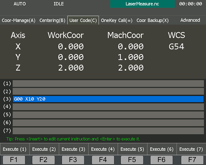
.To enter into User Code interface, press
 → C:
→ C:
To move the cursor to the target line, e.g. line (3), press ↑ / ↓.
Press Insert, and input a command.
To execute the command, do one of the following :
- Press F3.
- Press Enter.
Guide Machining by the Handwheel
This operation is used to manually control the automatic execution speed of the machining program during automatic machining, so as to guard against dangers caused by a wrongly loaded program or an inappropriate toolpath.
Before guiding machining by the handwheel, connect the handwheel.
To guide machining by the handwheel, do the following:
To enter into AUTO mode, press
 .
.To enter into Coor-Auto interface, press
 → A.
→ A.To enable handwheel guide, press F1.
To start machining by the handwheel, press
 .
.Turn the handwheel in the clockwise direction.
The system starts machining and stops machining within 300ms until you stop turning the handwheel.
Machining speed varies with the turning speed of the handwheel.