Main Software Interface
Through this part, you can quickly know the main software interfaces of WEIHONG NcStudio CNC System for Cutting Machines.
Main Interface of NcConfig Software
The main interface of NcConfig software is as follows:

- Menu bar
- Function display bar
- Configuration bar
Function Display Bar
You can do function commissioning in this bar after selecting the target function in the configuration bar.
Configuration Bar
In this bar, you can do the following:
Main Interface of NcTune Software
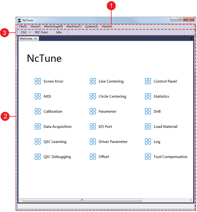
The main interface of NcTune software is as follows:

Menu bar
Welcome page
In the welcome page, you can do the following:
- Setting screw error compensation
- Inputting MDI
- Executing tool calibration
- Executing data acquisition
- Executing learning for the circularity test
- Doing commissioning for the circularity test
- Executing centering
- Setting parameters
- Setting port polarity
- Setting drive parameters
- Managing offsets
- Checking control panel
- Checking machining statistics
- Setting gang drilling
- Setting parameters for loading and unloading
- Checking logs
- Doing commissioning for the tool magazine
- Setting tool compensation
- Upgrading firmware
Status bar
Main Interface of NcStudio Software
The main interface of NcStudio software is as follows:

Title Bar
In this bar, you can check the following:
Weihong logo
Status of the control system
Current date and time
Hamburger menu

In the hamburger menu, you can achieve the following:
Status bar
In this bar, you can check the current operation mode, status, and tips or warnings.
You can double click the blank area to check different types of logs for troubleshooting, including information, warning, alarms. See Check System Logs for details.
Machine Control Bar
In this area, you can control the movement of the machine tool.
This bar is as follows:

Manual control bar
Buttons for axis direction: move each axis towards positive or negative direction.
Mode buttons
Jog
Click an axis direction button. The machine tool keeps running at jog speed until you release the button.
Click Rapid and an axis direction button. The machine tool keeps running at rapid jog speed until you release the button.
HW: select the axis direction and handwheel override gear in the handwheel, and rotate the control disk. The machine tool is controlled by the handwheel and the selected axis moves at the selected handwheel speed.
Step: click an axis direction button and release it. The machine tool moves the selected step size.
You can select the fixed step size among 0.01mm, 0.1 mm, and 1 mm or a customized step size (default: 5mm).
Note: Please do not set the step size to a too large value to avoid damage due to misoperation, and do not click an axis direction button too frequently because the system needs a certain time for response.
Coordinate display bar: check the workpiece coordinate, machine coordinate of each axis and the current workpiece coordinate system.
Speed control bar: adjust the spindle speed, feedrate and G00 speed, and check the current spindle speed and feedrate.
The relationship between the override and speed is as follows:
Current feedrate = Current feedrate override * Setting speedCurrent G00 speed = Current feedrate override * G00 setting speed
Function Control Bar
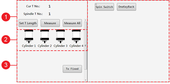
This bar is as follows:

Operations for tool calibration
Check the current tool number and tool number on the spindle.
Do tool calibration:
Set T Length: directly set tool offset of Z-axis.
Measure: do tool calibration.
Measure All: select several tools and do tool calibration.
Cylinder control bar: turn on / off the cylinders. At most four cylinders are supported.
Note: If no cylinder is selected in the configuration bar in NcConfig software, this bar will be hidden.
Customized function bar: show ports and functions configured by NcConfig software. See Set Machine Parts for details.
Operation Control Bar
Operations in this bar are as follows:
 : load a program file.
 : unload a program file.
 : do clearing for a single axis or all axes.
 : input MDI, including rapid movement and simple machining.
 : execute simulation. You can check the simulation track in Tool Path&Trace window to see if the toolpath exceeds the workbench stroke.
 : control the machine tool with the handwheel.
 : execute an optional skip of the program file, by customizing the start line and end line of the program block, so that you can freely select the machining range.
 : execute returning to the workpiece origin.
 : start machining.
 : pause machining.
 : stop machining.
 : resume machining from the exact interrupted position when power interruption or an E-stop alarm occurs.
Function Windows
Function windows include the following:
Tool Path&Trace: show the content of the loaded program file and the track during machining.
Multi-task Manage: manage and edit task files for multi-task machining.
Offset Manage: manage the workpiece offsets and public offsets.
Craftsmanship: show the current technics, and set related technic parameters.
Gang Drilling: add and orange the drilling in the drilling packages.