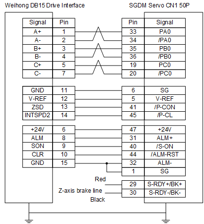
Wiring Diagram of the Drive
It is about how to connect WEIHONG DB15 drive interface to different servo motors.
Before connecting, you need to know the definition of each drive interface. See Definition of Drive Interface for details.
The wiring of a servo drive differs in the control mode. Thus, the wiring diagram of drive includes the following:
Wiring Diagram of the Drive (in Velocity Control Mode) (Exclusive for laser cutting industry)
Definition of Each Drive Interface
The socket of servo drive joint is three-row DB15 holes.
Its interface definition is shown as follows:
Position control
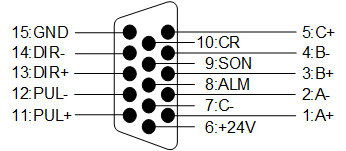
Velocity control

Remark of drive interface is as follows:
| Signal | Definition | Input/Output | Remark |
|---|---|---|---|
| A+, A- | Feedback signal of encoder phase A | Input Differential signal transmission mode |
It is used to receive the differential output of encoder phase A signal from driver frequency divider (equal to RS422). |
| B+, B- | Feedback signal of encoder phase B | Input Differential signal transmission mode |
It is used to receive the differential output of encoder phase B signal from driver frequency divider (equal to RS422). |
| C+, C- | Feedback signal of encoder phase C | Input Differential signal transmission mode |
It is used to receive the differential output of encoder phase C signal from driver frequency divider (equal to RS422). |
| ALM | Drive alarm signal | Input | When the drive detects failure, this output (transistor) switch will be closed or disconnected. |
| SON | Servo ON signal | Output | It is used to turn on (power on) and turn off (power off) servo motor. When it is connected to COM, dynamic brake will be released and the drive is allowed to work (servo enabled). |
| CLR | Drive alarm clear signal | Output | It is used to remove alarms/warnings. |
| PUL+, PUL- | Pulse output | Output Differential signal transmission mode |
- |
| DIR+, DIR- | Direction output | Output Differential signal transmission mode |
- |
| INTSPD2 | Internal command speed option 2 | Output | - |
| ZSP | Speed zero clamp detection signal | Output | In speed zero clamp detection status, the output transistor is turned on. |
| V-REF | Analog speed command | Output | - |
| +24V, GND | DC 24V power | Output | It is connected to drive. |
Wiring Diagram of the Drive (in Position Control Mode)
Please select the wiring diagram according to the brand of your servo drive:
- WISE Servo Drive
- YASKAWA Σ-Ⅱ/Σ-Ⅴ/Σ-7 Servo Drive
- Panasonic AC Servo Drive
- Fuji Servo Drive
- DELTA Servo Drive
- MITSUBISHI Servo Drive
- STONE GS Servo Drive
- HITACHI Servo Drive
- TECO Servo Drive
- SANYO Servo Drive
- KT270 Servo Drive
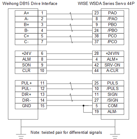
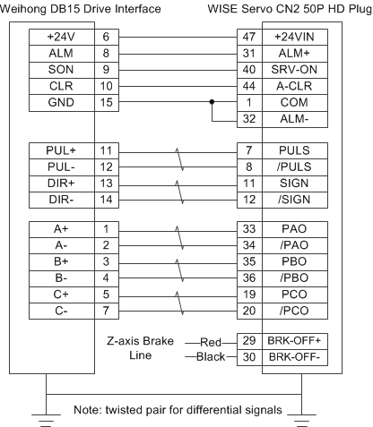
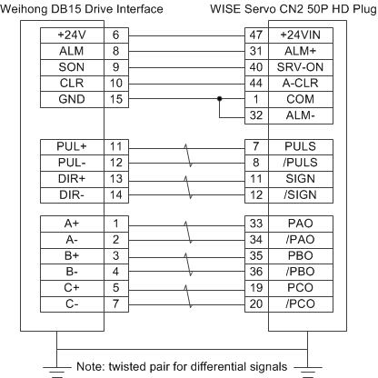
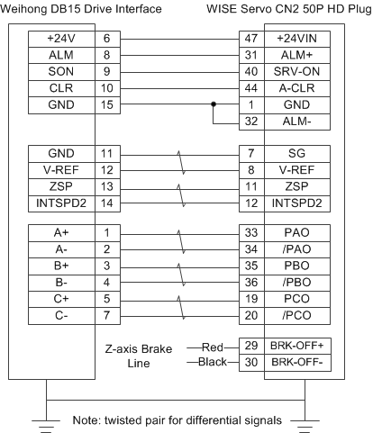
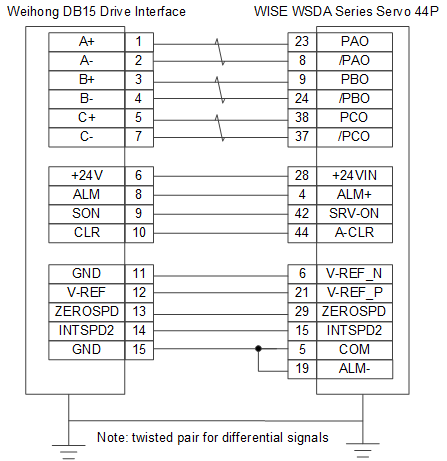
Wiring Diagram of WISE Servo Drive
The wiring diagram is as follows:
With brake lines (44P interface)

Without brake lines (44P interface)
With brake lines (50P HD plug)
Without brake lines (50P HD plug)
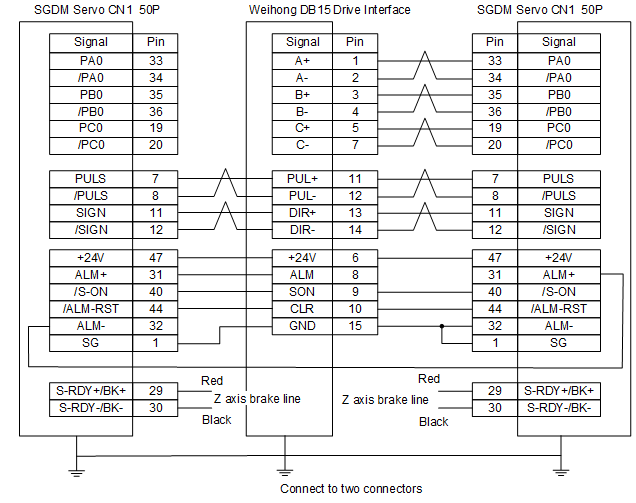
Wiring Diagram of YASKAWA Σ-Ⅱ/Σ-Ⅴ/Σ-7 Servo Drive
The wiring diagram is as follows:
Connect to one connector

Connect to two connectors
Wiring Diagram of Panasonic AC Servo Drive
The wiring diagram is as follows:

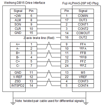
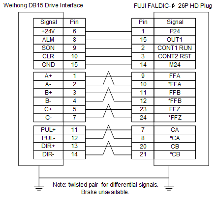
Wiring Diagram of Fuji Servo Drive
Wiring diagram is as follows:
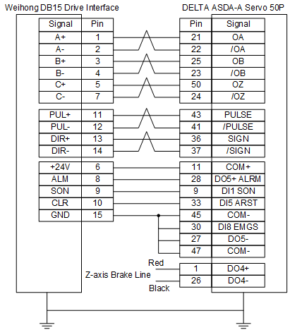
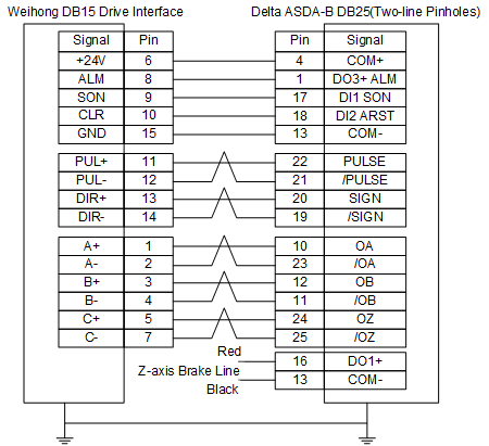
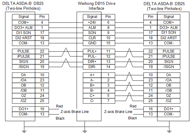
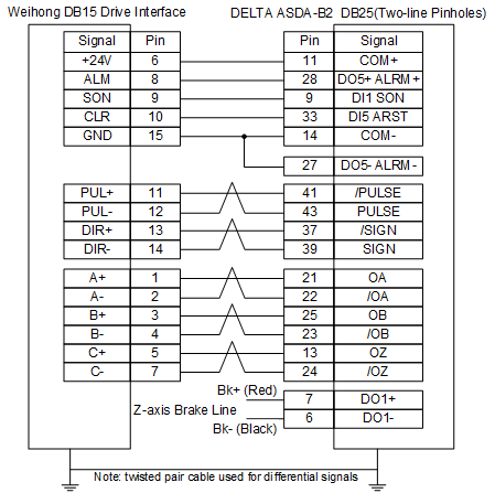
Wiring Diagram of DELTA Servo Drive
DELTA ASDA-A, ASDA-AB share the same wire. Among them, ASDA-A2 and ASDA-AB have the same wiring pin while ASDA-A has the contrary pulse pin, with PULSE 43, /PULSE 41.
The wiring diagram of DELTA ASDA-A servo drive is as follows:
DELTA ASDA-A
DELTA ASDA-B (connect to one connector)
DELTA ASDA-B (connect to two connectors)
DELTA ASDA-B2
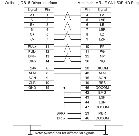
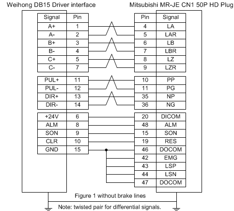
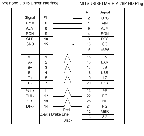
Wiring Diagram of MITSUBISHI Servo Drive
The wiring diagram is as follows:
MR-JE type (With brake lines)
MR-JE type (Without brake lines)
MR-E type
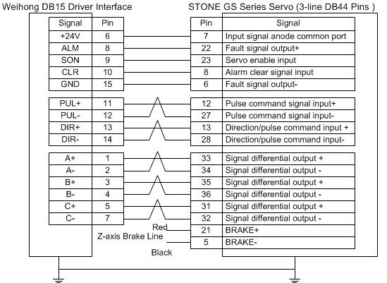
Wiring Diagram of STONE GS Servo Drive
The wiring diagram is as follows:
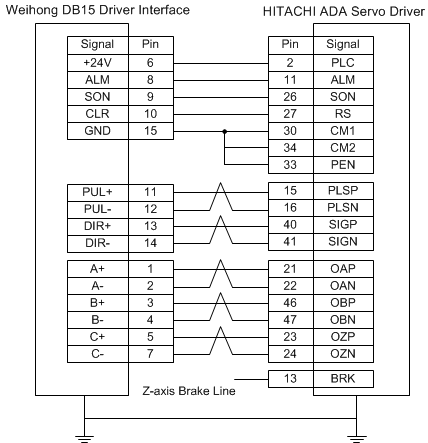
Wiring Diagram of HITACHI Servo Drive
The wiring diagram is as follows:
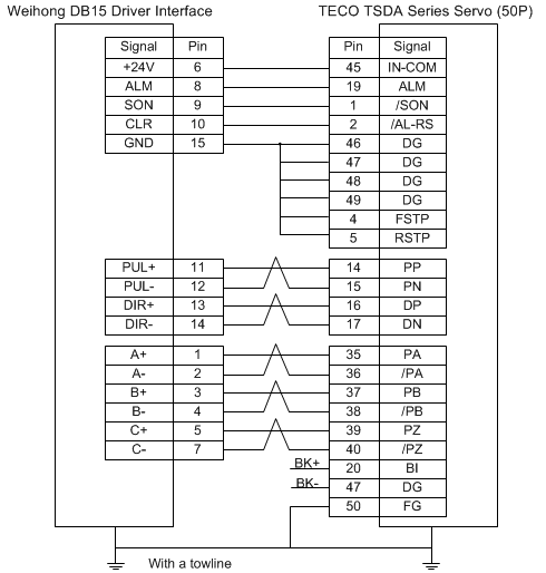
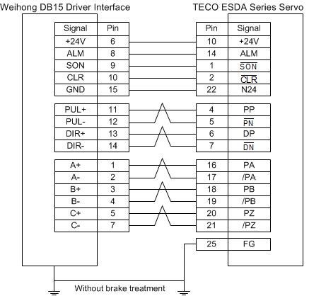
Wiring Diagram of TECO Servo Drive
The wiring diagram is as follows:
TSDA series
ESDA series
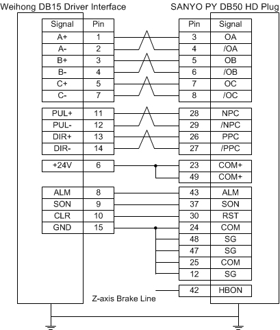
Wiring Diagram of SANYO Servo Drive
The wiring diagram is as follows:
PY series
R series

Wiring Diagram of KT270 Servo Drive
The wiring diagram is as follows:

Wiring Diagram of the Drive (in Velocity Control Mode)
Please select the wiring diagram according to the brand of your servo drive:
Wiring Diagram of WISE Servo Drive
The wiring diagram is as follows:
With brake lines (44P interface)

With brake lines (50P HD plug)
Without brake lines (44P interface)
Wiring Diagram of YASKAWA Σ-7 Servo Drive
The wiring diagram is as follows:
Wiring Diagram of Fuji Servo Drive
The wiring diagram is as follows: