Programming Terms
Absolute Command
With this command, programming value in every programming coordinate axis is the value equivalent to the origin of current workpiece coordinate system.
Canned Cycle
With the function of canned cycle, an action or a series of actions of hole machining, including drilling, boring, tapping etc. can be finished with just one program segment.
Counterclockwise Arc
It is the track rotated by reference point of tool resolving round track center at direction of positive angle.
Clockwise Arc
It is the track rotated by reference point of tool resolving round track center at direction of negative angle.
Cutting Speed
It is about the speed during cutting workpiece
Feed Function
Feed is that the tool moves at specified speed. The function of specifying feed speed is called feed function.
G94 and G95 are about feedrate. G94 means feed per minute; and G95 means feed per revolution. G94 is modal and once it is specified, it will keep effective until G95 is specified. When power is on, the setting is feed per minute.
Feed Hold
It is for interrupting feed function temporarily during machining program.
Function of Spindle Speed
It is the instruction to define technical specification of spindle speed.
Incremental Command
It is about the displacement that command tool moves from former position to the next position.
Interpolation
Interpolation is that the tool moves along lines and arc that compose the shape of workpiece during machining.
Machine Coordinate System (MCS)
It is the Cartesian coordinate system that is fixed on machine tool and on the basis of machine tool origin.
Machine Origin
Known as machine origin or machine zero point, or home position, the origin of MCS is confirmed and fixed after designing, manufacturing and tuning of machine.
The position of machine origin can’t be determined when a CNC device is powered on, and the mechanical stroke of each coordinate axis is limited by maximum and minimum limit switch.
Machine Reference Point
To set MCS correctly during machining, we normally set a machine reference point (the initial point of measurement) within the stroke range of each coordinate axis. After starting the machine, it is necessary to back to reference point manually or automatically so as to create the MCS.
The reference point can coincide with machine origin or not. If not, the distance from machine reference point to machine origin can be set through the relevant parameters.
After the machine returns to the reference point, the machine origin, which is the reference point of all coordinate axes, is confirmed, so the MCS is established.
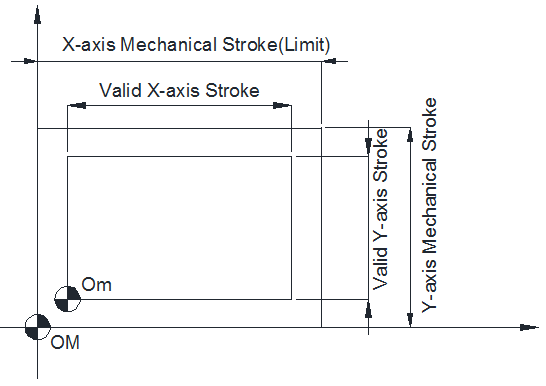
The stroke of MCS is defined by the machine tool manufacturer, while the valid stroke of MCS is defined by software limits.
The relationship between machine origin, machine reference point , the mechanical stroke and valid stroke of MCS is as follows:
Machine Tool Coordinate Axes
Basic coordinate axes
Linear feeding coordinate axes are denoted by X, Y and Z, which are normally referred to as basic coordinate axes. The correlation of X, Y and Z axes is determined by the Right-hand Rule as shown in the following:

The thumb points in the +X direction, the index finger points in the +Y direction, and the middle finger points in the +Z direction.
Rotary coordinate axes
Circle feed coordinate axes swiveling around X, Y and Z are respectively denoted by A, B, and C. According to the Right-hand Screw Rule, the thumb points in +X, +Y and +Z direction, while the index and middle finger points in +A, +B, and +C direction of circle feed motion.
The feed motion of CNC machine can be realized by spindle driving the tool or the worktable driving the workpiece. The positive directions of coordinate axes mentioned above are directions of tool feeding relative to the supposedly stationary workpiece. If the workpiece is kinetic, the coordinate axes are marked with single quote ’. According to relative motion, the positive direction of workpiece movement is opposite to that of tool movement, that is:
+X =-X’, +Y =-Y’, +Z =-Z’
+A =-A’, +B =-B’, +C =-C’
Likewise, their negative directions are contrary to each other.
The direction of machine coordinate axes
The directions of machine coordinate axes depend on the type of machine tool and the layout of each component. For a milling machine:
- Z-axis: it coincides with the main spindle axis, and the direction of tool moving away from workpiece is the positive direction (+Z).
- X-axis: it is perpendicular to Z-axis and parallel to the clamped surface of workpiece. For a single column vertical mill, if you face the spindle and look in the column direction, right moving direction is the positive direction of X-axis (+X).
- Y-axis: along with X-axis and Z-axis, it constitutes a coordinate system abiding by the Right-hand Rule.
Main Program and Subprogram
When the same machining mode appears several times in a program, the mode can be programmed into a program. This program is called subprogram and the original program is called main program.
Miscellaneous Function
It is for specifying machine tool part's start or stop.
Override
It enables operators to manually modify the programming value of speed (eg. feedrate, spindle speed and etc.).
Preparatory Function
It is the command of making machine tool or control system to set up machining function method.
Program Halt
It is for canceling spindle function and other function and terminating following miscellaneous function of data processing.
Stroke
On both sides of each axis equip limit switches to avoid tool moving out of range. The allowable moving range of tool is called stroke. Except using limit switch to set range, you can also use program or data in memory to specify the area that tool cannot enter into. The function is called stroke detection.
Structure of Machining Program
The group of commands that are sent to CNC system to run machine tool is called program. According to specified command, the tool moves along line or arc and spindle motor rotates or stops. A group of single-phase sequential commands is called program block. Program consists of a series of machining single block. The number used to distinguish program block is sequence number.
Tool Function
Every tool will be assigned a number. In program, specifying different number means selecting corresponding tool. When a tool is put in the station of ATC, you can selecting the tool through command Txx. The function is called tool function.
Tool Length Compensation
In general, several tools may be used in machining a part, and each tool has different length. Therefore, to avoid switch program according to tool in use, the length of each tool in use should be measured in advance and the length difference between standard tool and each tool should be set in CNC system. As a result, even the tool is changed, there is no need to switch program to achieve machining. The function is called tool length compensation.
Tool Track
It is the track moved by specified point in cutting tool.
Workpiece Coordinate System (WCS)
WCS includes workpiece coordinate systems in part drawing and specified by CNC system. To machine accurately workpeice into the shape in drawing, these two coordinate systems must be set in the same position.
Zero Offset
It is for the translation transformation of WCS during programming so as to make the programming coordinate system offset to a new position.