Product Introduction
VT310E is a position sensor controller based on EtherCAT communication. The preamplifier collects the capacitance information between the cutting head nozzle and the workpiece, and then analyzes and processes it through the control box. It can achieve real-time and precise positioning of position and height in high-speed motion.
System Connection
The system connection diagram is as follows:
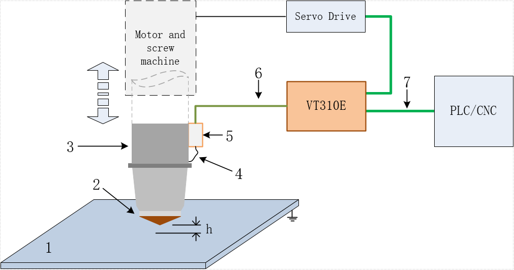
1.Workpiece to be machined 2.Cutting head nozzle 3.Cutting head body 4.RF cable 5.Precapacitor amplifier SE001 6.M16 three-core aviation cable (sensor signal cable) 7.EtherCAT connection cable h.Distance between nozzle and workpiece
Standard components include:
| Name | Quantity | Standard Model | Optional Specification |
|---|---|---|---|
| Control box | 1 | VT310E | - |
| Precapacitor amplifier | 1 | SE001 | - |
| RF cable | 1 | SMA/JW-SMA/J 200mm | - |
| M16 three-core aviation plug drag chain cable | 1 | 5000mm | □ 15000mm □ 20000mm □ 30000mm |
In order to build a complete system, the client also needs to configure:
A controller with EtherCAT master (such as PLC/CNC, communicating with VT310E)
A set of servo drives and motors that control follow-up axis motion (motion controlled by PLC/CNC)
A set of cutting heads (can be assembled with SE001)
VT310E
Product Appearance and Interface
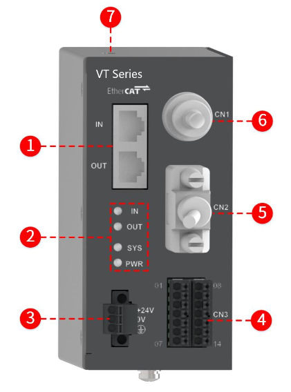
1.EtherCAT interface 2. Indicator light 3. Power interface *4. Input/output interface *5.Servo drive interface 6.Precapacitor amplifier interface 7.USB communication interface
*Note: 4 and 5 are used by other models of this system and are not supported by VT310E.
The interface functions are shown in the following table. For details, please see Interface Description.
| Name | Function |
|---|---|
| EtherCAT interface | Used for EtherCAT communication, transmission rate 100Mbps. IN is connected to the up EtherCAT master station, and OUT is connected to the next EtherCAT slave machine. |
| Indicator light | Used to indicate controller status. PWR is the power indicator light, indicating whether the power supply is normal. SYS is the system indicator light, which can identify different states: ∎ Flashing frequency 0.33Hz: EtherCAT is in non-OP state; ∎ Flashing frequency 2Hz: EtherCAT is in OP state and can communicate; ∎ Flashing frequency 10Hz: Hardware self-check failed; ∎ Flashing frequency of 1Hz and 3Hz alternately: XML (ESI) file reading failed; IN and OUT are EtherCAT indicators. If they are on, they are connected. If they flash, they are communicating with each other. |
| Power interface | For connecting to 24VDC power supply. |
| Precapacitor amplifier interface | For connecting precapacitor amplifier SE001. |
| USB communication interface | Connect to the host and communicate with the debugging software iFollow for realizing internal debugging, firmware upgrade and other functions. |
Installation Dimension
The front view and side view are as follows (unit: mm):
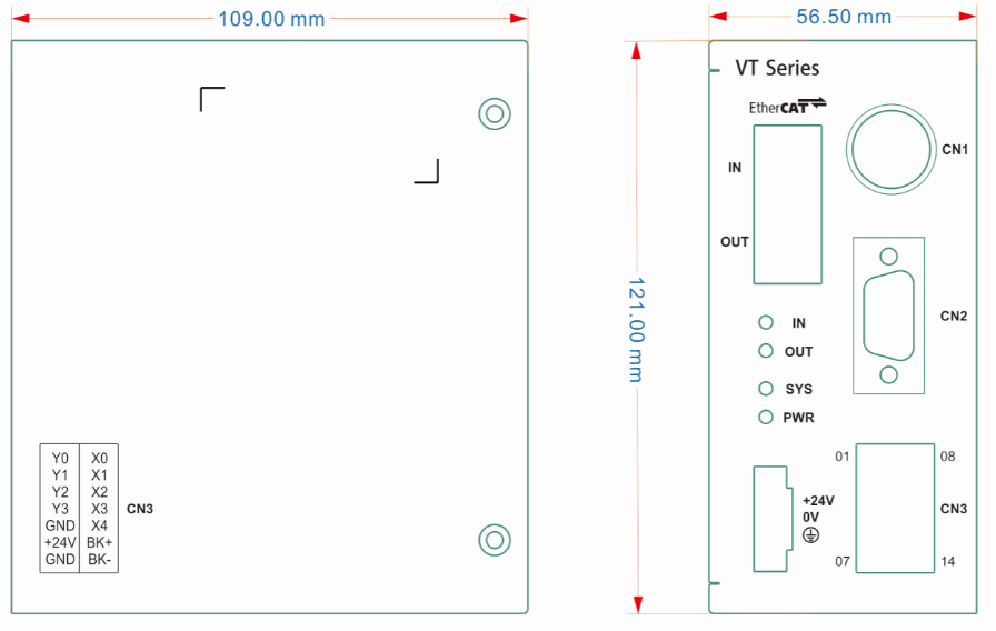
Installation method:
The VT310E structure is pre-installed with DIN rail fixed buckles on the back, which can install 35 * 7.5mm (width * depth) rail.
Preamplifier SE001
Product Appearance and Interface
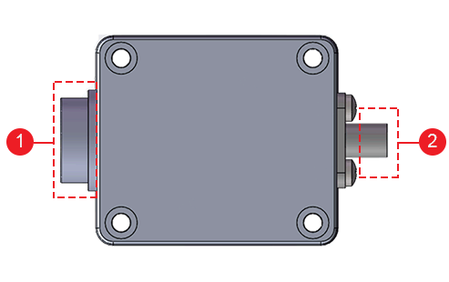
1.M16 aviation cable interface 2.SMA RF cable interface
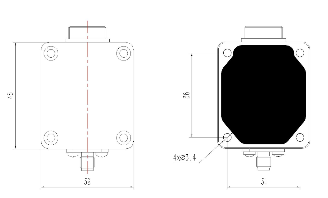
Installation Dimension
SE001 front view and rear view (dimension drawing) are as follows (unit: mm):
Features
- Support 16-point capacitance calibration
- Calibration height can be flexibly set by SDO
- Active identifies various anomalies in the calibration process (such as excessive fluctuations in capacitance values or wrong trends, etc.)
- Support nozzle loss point calibration, can realize detect real-time alarm for over-range and nozzle loss
- According to calibration data and real-time capacitance sampling value, accurate calculation and feedback of current height information
- Open multiple detection threshold parameters for users to set, which can be compatible with different application scenario needs
- Provide system running status and fault information to facilitate diagnosis and analysis
- The SYS indicator light on the panel can quickly identify whether the system is running normally
- Specific internal running status (calibration/measurement/debugging, etc.) can be read through SDO
- Alarm information can be obtained through PDO combination
- Support firmware online update
Specification Parameter
| Specification Name | Parameter Value |
|---|---|
| Supply voltage | 24VDC ± 10% |
| Measurement range | 0.1 ~ 25mm (the measured maximum value is limited by calibration height) |
| Control cycle | 1ms |
| Working temperature | 0℃~55℃ |
| Working humidity | 10%~95% (no condensation water) |
| Storage temperature | -40℃~70℃ |