Interface Description
Power Interface
The power interface is a three-core terminal, and each pin is defined as follows:
| Name | Description |
|---|---|
| +24V | 24 V or output connected to DC power supply |
| 0V | Connect to 0V/COM or negative terminal of DC power supply |
| PE | Connect the ground wire of the machine tool Note: Please do not connect the PE terminal to the neutral wire of the power supply line. |
EtherCAT Interface
The EtherCAT interface contains two Ethernet ports, IN and OUT.
| Name | Description |
|---|---|
| IN | Connect to the OUT of the EtherCAT master station or upper-level slave station |
| OUT | Connect the IN of the next-level EtherCAT slave station |
Capacitor Amplifier Interface
The sensor M16 interface is shown follows.
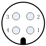
For the pin number definition of the sensor M16 interface, see the follows:
| Pin No. | Definition |
|---|---|
| 1 | +5 V: power supply |
| 2 | GND: power ground |
| 3 | SIG: signal |
| 4 | PE: shield layer |
USB Interface
Connect to a computer with the VT310E debugging software iFollow installed to update the firmware.