Auxiliary Editing
You can do the following for better effects of object editing:
- View objects
- Set catch options
- Select objects
- Measure distance
- Check the objects
- Switch to the fill mode
View Objects
It is used for a better view of objects without changing the actual sizes and coordinates.
It includes the following:
Pan the View
It is used to reposition the drawing window by selecting a base point and a second point for the new position.
To pan the view, do one of the following:
Press the mouse wheel and drag the mouse at the same time to move the view to the target position.
Do one of the following to call Pan command, and hold the left mouse button to move the view to the target position:
In the drawing toolbar, click
 Pan.
Pan.In the menu bar, click View → Pan.
To stop panning the view, right click or press Esc.
Zoom in/out the View
It is used to zoom in or zoom out the view. Through changing the size of the shown area and objects, you can draw objects more precisely
To zoom in/out the view, do the following:
To call Zoom command, in the menu bar, click View → Zoom.
Do one of the following:
Scroll up the mouse wheel to zoom in the view and scroll down the mouse wheel to zoom out the view.
Hold and drag up the left mouse button to zoom in the view, and hold and drag down the left mouse button to zoom out the view.
On the numeric keypad, press + to zoom in the view, and press - to zoom out the view.
To stop Zoom command, right click or press Esc.
Zoom in the Selected Area
It is used to zoom in the selected part of the object to the size of the drawing window.
To zoom in the selected area, do the following:
To call Zoom by Rect command, do one of the following:
In the drawing toolbar, click
 Zoom by Rect.
In the menu bar, click View → Zoom by Rect.
Left click on the drawing window, drag the mouse to form a rectangle and left click again. The area formed by the rectangle zooms in.
Fit to Window
It is used to resize objects and make them fit to the drawing window on the premise of showing all objects.
To fit to window, do one of the following:
In the drawing toolbar, click
 Best View.
In the menu bar, click View → Best View.
On the numeric keypad, press *.
Set Catch Options
It is used to precisely locate feature points and connect objects during drawing an object.
Once the cursor moves close to the feature points, the system can easily locate to the points.
To set catch options, do the following:
To open Catch Option dialog box, do one of the following:
In the common toolbar, click
 Catch Options.
-
- In the menu bar, click Drawing → Catch Options.

Check the feature items according to the shape of the object.
Adjust the catch sensitivity.
It is easier to get the feature points with higher catch sensitivity.
Optional: If Custom is checked in Polar Axis area, to set the incremental angle, do the following:
In the menu bar, click Drawing → Polar IncAngle. Polar Axis Inc. Angle dialog box pops up.
Check Enable and set the incremental angle.
The system catches feature points based on the set incremental angle.
When the system rotates the set angle, a polar axis line appears.
To enable catching function, do one of the following:
In the common toolbar, click
 Catch.
In the menu bar, click Drawing → Catch.
Select Objects
It is used to select objects for editing.
To select objects, do one of the following:
Manually Select Objects
To manually select objects, do the following:
In the drawing toolbar, to call Select graph command, click
 Select graph.
Do one of the following:
To select a single object, left click the target object on the drawing window.
To select several objects, press Ctrl and left click the target objects one by one.
To select objects contained in the selected area, hold the left mouse button to drag from upper left to lower right.
Objects intersected with the area will not be selected.
To select objects intersected with or contained in the selected area, hold the left mouse button to drag from lower right to upper left.
Automatically Select Objects
To automatically select objects, do one of the following:
Click
Select in the common toolbar, or click Edit → Select in the menu bar, and select one of the following in the drop-down box:Select All:
Select Invert:
Select Unclosed: to automatically select all unclosed objects.
Select Tiny: to automatically select all objects within the target size.
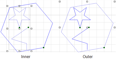
Inner:
Outer:
Select Similar: to select all the similar objects after selecting one object, ignoring the difference of angle.
Select Similar(Strict in angle): to select all the similar objects after selecting one object, paying attention to the difference of angle.
In the menu bar, click Edit, and select one of the following:
Select by Layer: to automatically select all objects within the same layer.
Select by Inner-Outer: to automatically select objects based on the nesting (inner: select inner objects; outer: select outer objects):
Select by Type: to automatically select objects of the same type.
Measure Distance
It is used to measure distance, X-axis / Y-axis offset and the vector angle between two points.
To measure distance, do the following:
To call Measure command, do one of the following:
In the drawing toolbar, click
 Measure.
In the menu bar, click View → Measure.
Left click to select the start point for measuring, and move the cursor to select the end point.
The measurement result shows near the end point.
Check the Objects
It is used to examine the imported or drawn objects to see if there exist unclosed / self-intersected / intersected / overlapped objects.
To check the objects, do the following:
In the menu bar, click View → Graphic Detection. Shape Check dialog box pops up:
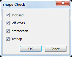
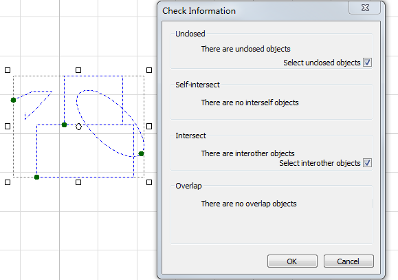
Select the target checking items.
After checking the objects, Check Information dialog box pops up:
Switch to the Fill Mode
It is used to view closed objects that are set as Fill. In the fill mode, objects set as Fill are filled in while and others are shown in the wireframe.
All objects are shown in the wireframe by default.。
To switch to the fill mode, in the menu bar, click View → Fill Mode:
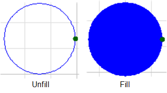
To switch to the wireframe mode, in the menu bar, click View → Wireframe Mode.