Set Scan Cutting
It is used to replan a toolpath to find the most efficient path to execute machining by controlling laser on/off, so as to avoid unnecessary tool lifting and feeding and improve machining efficiency.
It differs in the object type:
- Set scan cutting for lines.
- Set scan cutting for arcs.
- Set scan cutting for LED advertisement words.
- Set scan cutting for runways.
- Set scan cutting for sectors.
- Set scan cutting for rings.
Set Scan Cutting for Lines
To set scan cutting for lines, select the target objects, and do the following:
To open Line Scan pops up, do one of the following:
In the common toolbar, click
 Scan.
Scan.In the common toolbar, click the drop-down box of
Scan, and select Line Scan.In the menu bar, click Planning → Scan → Line Scan.
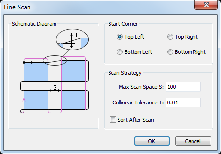
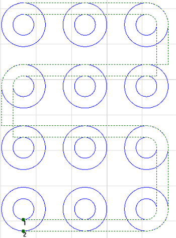
Select the start position for cutting, and set the following parameters:
Max Scan Space: if the distance between objects sharing a common edge is greater than the set value, objects will be divided into two groups to do scan cutting.
Colinear Tolerance: if the distance between two parallel lines in objects is less than the set value, the two lines will be regarded as a common edge.
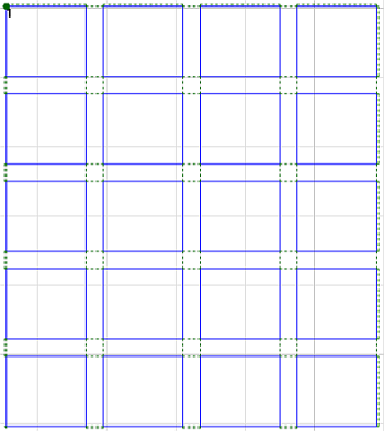
The result is as follows:
Set Scan Cutting for Circles
To set scan cutting for circles, select the target objects, and do the following:
To open Arc Scan dialog box, do one of the following:
In the common toolbar, click the drop-down box of
Scan, and select Arc Scan.In the menu bar, click Planning → Scan → Arc Scan.
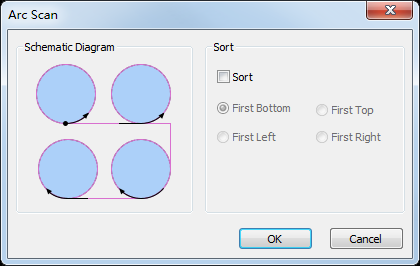
Optional: To select a sorting strategy, check Sort.
Default sorting strategy: Out -> In.
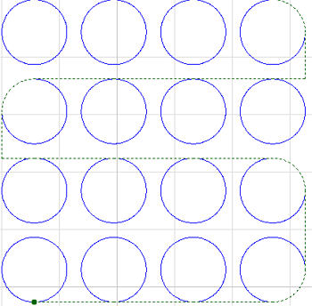
The result is as follows:
Set Scan Cutting for LED Advertisement Words
To set scan cutting for LED advertisement words, select the target objects, and do the following:
To open LED Scan dialog box, do one of the following:
In the common toolbar, click the drop-down box of
Scan → LED Scan.In the menu bar, click Planning → Scan → LED Scan.
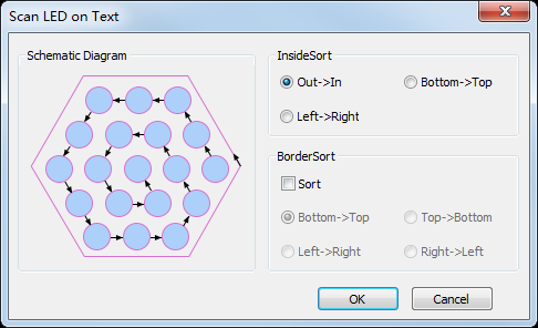
Set a sorting strategy:
Inside Sort: to sort all circles in the inner of the target objects, and form a scanning group.
Border Sort: to sort objects based on the frames of the target objects.
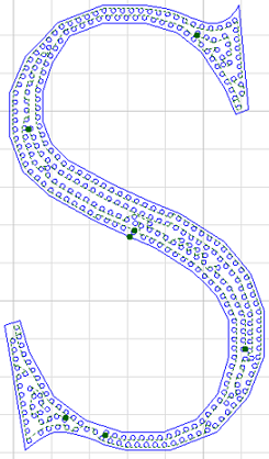
Taking sorting strategy Inside Sort as an example, the result is as follows:
Set Scan Cutting for Runways
To set scan cutting for runways, select the target objects, and do the following:
To open Runway Scan dialog box, select one of the following:
In the common toolbar, click the drop-down box of
Scan → Runway Scan.In the menu bar, click Planning → Scan → Runway Scan.
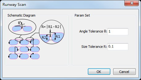
Set the following parameters:
Angle Tolerance: if the angle difference is less than the set tolerance, the target objects are parallel. Range: 0°~5°.
Size Tolerance: if the height difference between two runways is less than the set tolerance, the sizes of target objects are the same. Range: 0mm~1mm.
The result is as follows:
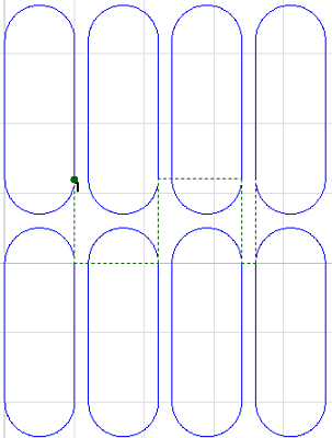
Set Scan Cutting for Sectors
To set scan cutting for sectors, select the target objects, and do the following:
To open Sector Scan dialog box, do one of the following:
In the common toolbar, click the drop-down box of
Scan → Sector Scan.In the menu bar, click Planning → Scan → Sector Scan.
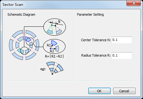
Set the following parameters:
Center Tolerance: if the distance between circle centers of two circular rings is less than the set tolerance, the target objects are in a scanning group.
Radius Tolerance: if the radius difference between two circular rings is less than the set tolerance, the target objects are in a scanning group.
The result is as follows:
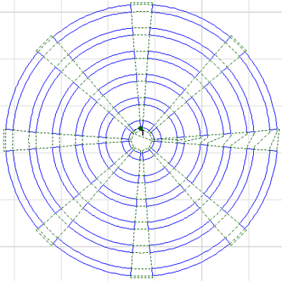
Set Scan Cutting for Rings
To set scan cutting for rings, do the following:
To open Ring Scan dialog box, do the following:
In the common toolbar, click the drop-down box of
Scan.In the menu bar, click Planning → Scan → Ring Scan.
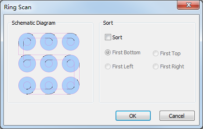
Optional: Check Sort and select the sorting direction.
The result is as follows: