Software Interface
Through this part, you can quickly know the layout of the main interface for NcStudio V15 Laser Cutting CNC System.
The main interface is as follows:
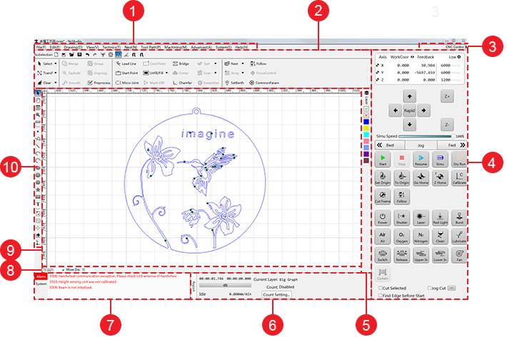
- Menu bar
- Common toolbar
- Control bar display button
- Machine control bar
- Layer toolbar
- Statistics bar
- Alarm/system info bar
- Drawing information bar
- Drawing window
- Drawing toolbar
Common Toolbar
It is used to show the following frequently used instructions:
 New: to create a new toolpath file.
 Import: to import a
 DXF/DWG/PLT/G/NCfile. Open: to open a
 NCEXfile. Save: to save a toolpath file as a
 NCEXfile. Undo: to go back to a previous state by reversing the effects of one or more commands.
 Redo: to do over again.
 Show order: to show the machining order.
 Show direction: to show the machining direction.
 Highlight unclosed objects: to mark all unclosed objects with red color.
 Clear trace: to clear the machining trace.
 Catch: to enable catching function.
 Catch options: to set options for catching.
 Select: to select all objects, deselect selected objects, cancel selected objects, and select unclosed objects, tiny objects, inner objects, outer objects and similar objects. See Select Objects for details.
 Transform: to translate objects, rotate objects, vertically or horizontally mirror objects. See Translate Objects, Rotate an Object and Mirror Objects for details.
 Clear: to clear some set technics. See Do Clearing for details.
 Merge: to combine several objects as one object. See Merge Objects for details.
 Explode: to trim the toolpath. See Explode Objects for details.
 Smooth curve: to make polylines flat and even. See Smooth Curves for details.
 Group objects: to bind several objects as a group. See Group Objects for details.
 Ungroup objects: to separate the grouped objects. See Ungroup Objects for details.
 Preprocess: to preprocess several target objects with one click. See Preprocess with One Click for details.
 Lead line: to set a lead-in and lead-out lines. See Set a Lead Line for details.
 Start point: with a lead line: to set the start point of the lead line; with no lead lines: to set the current point as the start point.
 Micro joint: to reserve the set distance without machining and connect the workpiece and sheet. See Execute Micro Joint for details.
 Unfill / fill: to set unfill (reserve the outer part) or fill (reserve the inner part). See Set Fill or Unfill for details.
 Mach direction: to show and modify the machining direction. See Change the Machining Direction for details.
 Bridge: to connect two objects with a bridge. See Bridge Objects for details.
 Compensate: to compensate the kerf in the actual machining. See Set Kerf Compensation for details.
 Chamfer: to add a chamfer. See Add a Chamfer.
 Sort machining order: to show and modify the machining order. See Change the Machining Order for details.
 Scan cut: to replan the toolpath to find the most efficient path for machining, so as to avoid unnecessary tool lifting and feeding and improve machining efficiency. See Set Scan Cutting for details.
 Instant setting: to set fill/unfill, lead lines, machining direction, machining order and kerf compensation with one click. See Execute Instant Setting for details.
 Nest: to do nesting to improve sheet utilization and machining efficiency. See Nest for details.
 Array: to copy machining objects according to the set arraying way. See Execute Array for details
 Set berth: to open Set Berth Point dialog box. See Set the Workpiece Origin for details.
 Follow: to calibrate the cutting head. See Calibrate Capacitance for details.
 Common param: to set frequently used parameters, including machine parameters, following-up parameters and units. See Common Parameters for details.
Control Bar Display Button
You can show/hide the machine control bar by clicking CNC Control in the upper right corner.
Machine Control Bar
It includes the following:
Axis Coordinate Display Bar
It is shown as follows:
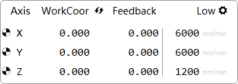
After returning to the machine origin, sign  appears in front of each axis.
In this bar, you can do the following:
To switch between workpiece coordinates and machine coordinates, click
 .
.To separately set low speed, rapid speed and step size for X/Y-axis and Z-axis, click
 , and set them in Manual Speed Setting dialog box:
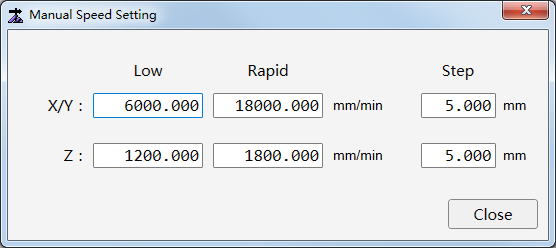
Manual Control Bar
It is shown as follows:

Axis direction buttons: to move each axis towards positive or negative direction.
Simulation speed: to adjust the simulation speed, select one of the following:
Drag the slider.
Click the slider and press PgUp / PgDn or ↑ / ↓ / ← / → on the keyboard.
Movement control button: to control the machine tool to move backwards (Bwd button) / move forwards (Fwd button) along the toolpath:
In Jog mode, click and hold the button. The machine tool keeps moving until you release it.
In Step mode, click the button. The machine tool only moves the set step size.
Feed mode buttons
Jog mode (default mode): in this mode, click and hold an axis direction button or several axis direction buttons. The clicked axis/axes move(s) at jog speed until you release the button(s).
In this mode, click Rapid, click and hold an axis direction button or several axis direction buttons. The clicked axis/axes move(s) at rapid jog speed until you release the button(s).
Step mode: in this mode, click an axis direction button. The clicked axis moves the customized step size (default: 5mm).
In this mode, to customize the step size, click
in the axis coordinate display bar.
Note: Please do not click an axis direction button too frequently because the system needs a certain time to respond.
Machining Control Bar
It includes the following:
 : to start machining from the beginning of the toolpath file.
 : to stop machining.
 : to resume machining from the exact interrupted position when the power interruption or E-stop occurs and the machine coordinate is correct.
 : to execute simulation to check the toolpath in real-time.
 : to run the machine tool without turning on related ports of laser and machining. There is no actual machining.
 : to set the workpiece origin.
 : to control the cutting head to return to the workpiece origin.
 : to return all axes to the machine origin.
 : to return Z-axis to the machine origin.
 : to calibrate the cutting head.
 : to confirm the machining range by running the system along the frame of the toolpath.
 : to do commissioning for the follow-up control system.
 : to turn on the laser power before machining.
 : to manually turn on laser shutter.
To eject laser light, first, turn on the laser shutter; then, turn on the laser.
 : to turn on/off the laser. When machining starts, the system will automatically turn on the laser.
 : to manually turn on the red light, which is used as a kind of guide light to guide the laser position on the sheet.
 : to turn on the laser for a certain time. The system will automatically turn on the laser for the set burst time and turn it off.
 : to blow air. When machining starts, the button will be highlighted, and the system will automatically turn on the blowing valve and blow air.
 : to blow oxygen. When machining starts, the button will be highlighted, and the system will automatically turn on the blowing valve and blow oxygen.
 : to blow nitrogen. When machining starts, the button will be highlighted, and the system will automatically turn on the blowing valve and blow nitrogen.
 : to set automatic nozzle cleaning. See Set Nozzle Cleaning for details.
 : to turn on lube.
 : to automatically exchange the workbench, so as to improve machining efficiency.
 : to release the workbench during manually exchanging the workbench.
 : to control the upper workbench entering the machining area, so as to improve machining efficiency.
 : to control the lower workbench entering the machining area, so as to improve machining efficiency.
 : to turn on the fan. The system will control whether to automatically turn on the fan when machining starts and turn off fan when machining ends through system parameters Fan On at Machining Start and Fan Off at Machining End.
Machining Selection Bar
You can check the following in the bar:
Cut Selected: with it checked, the system will only execute machining, dry run, simulation, frame cutting and breakpoint resume for the selected objects.
Jog Cut: with it checked, the laser will keep on during manually moving the axis for a certain distance. After jog cutting ends, the checking status will be canceled by default, and the laser will not be automatically turned on during the next machining.
Find Edge before Start: with it checked, the system will automatically find edges of the sheet before machining.
Layer Toolbar
You can do the following operations related to layer:
 : to open Layer dialog box. See Layer Interface for details.
 : to include the selected object(s) during machining.
 : to exclude the selected object(s) during machining. At this time, the object(s) turn(s) to white.
 : to convert the color of the selected objects into the color of the selected layer.
Statistics Bar
It is shown as follows:

You can do the following in the bar:
Open Statistic Information dialog box by clicking Report. See Check Statistics for details.
Open Count Setting dialog box by clicking Count Setting. See Count Machining for details.
Check the machining time, current layer, machining count, system status and machining speed.
Alarm/System Info Bar
It is shown as follows:
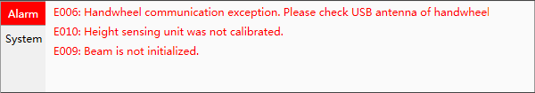
You can do the following in the bar:
Open Log dialog box by double clicking Alarm / System. See Check System Logs for details.
Troubleshoot the alarm or check the log details by double clicking the related alarm item or system information item.
Drawing Information Bar
It is shown as follows:

You can check the following in the bar:
Scaling of the drawing window
Tuning distance
Information of current drawing objects, including drawing steps and meaning, step result, etc.
Drawing Window
You can draw and preview objects in this window.
Drawing Toolbar
You can do the following in the toolbar: