View Technic
In order to achieve efficient utilization of residual materials, the following functions are provided:
Surplus: After drawing the contour track for the remaining plates, add them to the plates.
Cut line: After cutting, draw the cut-off line according to the actual situation to retain the uncut p to the maximum extent.
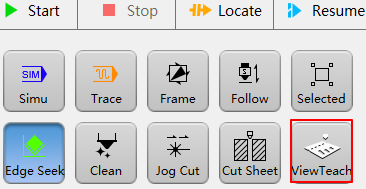
Function Entry
Machine Tool Control Bar → View Teach, as shown in the figure below:
Function interface display:
Prerequisite
Make sure that the cutting head (Z-axis) has been moved to a safe position to avoid cutting head collision during track drawing.
Make sure the X and Y axes have returned to machine origin.
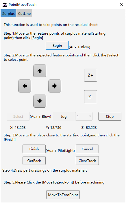
Surplus
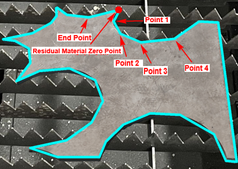
The actual residual material plate generates the residual material contour, which is a closed graphic, thus forming the residual material plate, which is convenient for the user to draw part drawings on the residual material plate.
Operation Steps:
Open the Surplus interface, located in the Surplus bar of View Teach:
Move the cutting head to the desired start point of the residual material and click Begin. This point will be set as the residual material zero point.
Move the cutting head according to the residual material track, and click Select on the corresponding residual material point to draw the residual material track.
If the position of the current point selected during point selection is not as expected, you can click Get Back. This will cancel the last selected point and you can reselect the desired point.
After selecting points, click Finish. A line will be automatically generated between the last selected point (end point) and the start point, turn the residual material track into a closed figure.
If the final generated track is inconsistent with the track we want, we can directly select the generated track and click Clear Track, so that the selected residual material track will be cleared and can be redrawn.
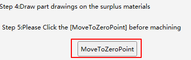
After the track is drawn, click Move to Zero Point, and the cutting head will automatically move to the zero point position of the residual material.
For residual material plate nest, machining can be started directly after the nest is completed.
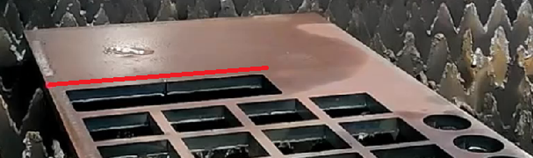
Cut Line
This function can form irregular boundaries based on the actual cutting conditions of the plate. Draw the corresponding cut-off line according to the actual boundary conditions, so that the maximum amount of uncut plate can be retained to achieve the purpose of efficient utilization of residual materials.
Related System Parameter
Parameter name:
One Click Cut Board Manual Cut-off Line Normal Graphic Stratogy
Parameter position:
System Parameters → Advanced Function → Other Param → Cut Sheet → One Click Cut Board Manual Cut-off Line Normal Graphic Stratogy
Parameter meaning:
Define the method of cut-off line end cutting end: 0 (not detect out margin signal); 1 (detect out margin signal).
When the Value is 0:
If the cut-off line track drawn is short and the cut-off line end point is on the plate (as shown below). When cutting reach the cut-off line end point, the cutting will stop and the Z-axis will lift.
If the drawn cut-off line track exceed the plate boundary, cutting will also stop when the plate is cutting, and the Z-axis will lift.
When the Value is 1:
If the cut-off line drawn is shorter and the cut-off line end point is on the plate, the cutting will not stop when it reach the cut-off line end point, but will continue to cut along the exceed of the last cut-off line until cut out the plate boundary.
If the drawn cut-off line exceed the plate boundary, cutting will also stop when the out margin signal is detected during cutting.

Operation Step
Open the Cut Line interface, located in the Cut Line bar of View Teach:
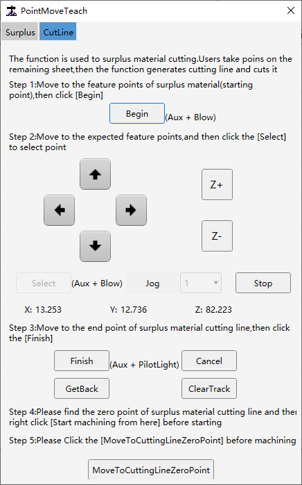
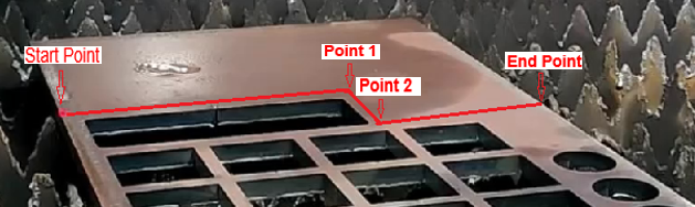
Move the cutting head to the start point of the desired cut-off line and click Begin. This point will be set as the cut-off line start point.
Move the cutting head to the next point and click Select, select the appropriate cut-off line point based on the actual plate position, and draw the appropriate cut-off line track.
If the position of the current point selected during the point selection process is not as expected, you can click Get Back. This will cancel the last point selected and you can reselect the desired point.
After selecting the points, click Finish. The cut-off line track will be drawn, and the cut-off line track will become a large layer track (use the large layer technic when cutting).
If the final generated track is inconsistent with the track we want, we can directly select the generated track and click Clear Track, so that the selected residual material track will be cleared and can be redrawn.
After the cutting head is positioned at the cut-off line start pont, click Start in the machine tool control bar. The system will cut along the drawn cut-off line track and cut-off the residual material.
Caution
Cutting cut-off line use the large layer technic by default. If other technics are required for actual cutting, the technic can be modified first and then started.