Machine Tool Control Bar
The machine tool control bar includes:
Coordinate Display Area
Display the workpiece coordinates, machine coordinate, feedback coordinate, low speed, rapid speed and step distance of each axis:

After the return to machine origin is successful,  mark will appear in front of each axis.
In this area, can perform the following operations:
Click
 to switch between workpiece and machine coordinates.
Click
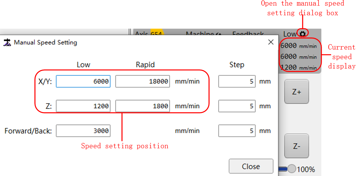
 to set the low speed, rapid speed and step distance of the X/Y-axis and Z-axis separately:
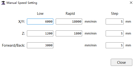
Manual Axis Control Area
Axis description:
X/Y-axis: The X/Y-axis is the axis that control the forward and back/left and right motion of the cutting head (the control mode use position loop control).
Generally, the Y-axis is used to control the gantry axis and is divided into two drives, Y1 and Y2. The X-axis is generally used to control the cutting head to move left and right. There are also situations where the X-axis is used to control the gantry axis, such as the "Bond" machine tool. At this time, the gantry axis is divided into two axes: X1 and X2.
Z-axis: Z-axis is the follow-up axis (the control mode is speed loop control), which is used to control the cutting head up and down motion.
Manual motion is divided into two types: jog and step mode. The switches for the two modes are as follows:

When using the handle to switch manual jog/step, press the Step button to switch.
Jog Mode
There are two modes: Rapid and Low in manual jog mode. The switching path is as follows:

Caution
When using the handle to switch manual Rapid / Low, need to keep pressing the Rapid button on the handle. After releasing it, the current mode will change to the mode set on the software interface.
The corresponding rapid/low motion speed can be set according to different speed needs:
It can be set in the system parameters. The specific setting position is: System Parameters → Speed Accuracy → 2.0 Jog Speed → 2.0.0 Jog Speed.

After setting the motion mode and speed, click the direction keys to move the corresponding axis for movement.
Manual Step
Manual step mode can set the corresponding step distance to move the target axis to the desired position.

The speed of manual step is set in the system parameters. The specific setting position is: System → System Parameters → Speed Accuracy → 2.0 Jog Speed → 2.0.0 Jog Speed.

After setting the manual step distance and speed, click the direction key corresponding axis will move to a step distance position. It cannot be executed when manual movement is executed again during the movement. Only after step into the arrival target position, the system enter idle state can execute the next action.
Override Adjust
There is an override adjust function in the operation bar, which can adjust Auto Frp and SIM Frp.

- Auto Frp
Auto Frp adjust the speed of non-simulation motion. The adjusted machining override not only affect the speed during machining but also affect the speed of manual motion.
Actual movement speed = set speed × machining override
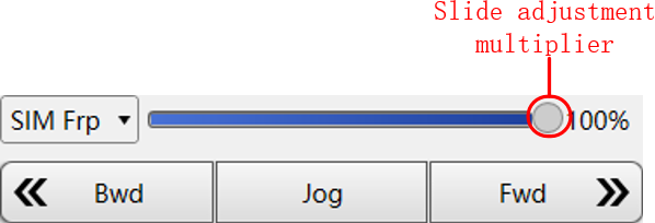
- SIM Frp
SIM override is only effective for simulation machining and has no effect on other motion forms.
Actual SIM speed = SIM speed × SIM override
When simulating motion, the machine tool is not controlled to execute corresponding machine electrical actions, and only the machining trajectory is displayed in the object edit area. The trajectory running speed is the simulation speed. If you want to accelerate simulation speed, in addition to modifying the simulation override, you can also modify the cutting speed in the layer.

Machine Tool Control Button
Start and stop machining and execute and laser cutting related operations:
| Button | Description |
|---|---|
 |
Set the workpiece coordinate of the current coordinate system to zero. |
 |
Return to workpiece origin. |
 |
Execute all axes to return to machine origin. |
 |
Execute the Z-axis return to machine origin. |
 |
Calibration refer to capacitance calibration. Its main function is to collect capacitance data and match the relationship between the distance between the cutting head and the cutting plate and the capacitance feedback of the cutting head. |
 |
Start the machining task from the beginning. |
 |
Stop this machining task. |
 |
After machining stop, if the machine coordinates are ensured to be accurate, machining will resume from where the last machining stopped. If set system parameter Break Distance When Breakpoint Continues, then resume machining from (last machining stop + breakpoint resume back distance). |
 |
When machining stop, click this button to position the last machining stop point. If set system parameter Break Distance When Breakpoint Continues, then resume machining after positioning to (last machining stop point+ breakpoint resume back distance). |
 |
Enter simulation mode. The system does not drive the machine tool to perform corresponding machine electrical action and only high speed simulate the machining path in the drawing area. |
 |
Enter track mode. Run the machine tool without open the laser and machining related ports to check whether the machining action is correct. |
 |
The laser head walk around the outer frame of the graphic to be machined and create a rectangle, which is used to determine the machining range and position of the plate. The speed of cut frame is set in System → Common Parameters → Machine Param → Frame Check Speed. |
 |
During machining, only the selected graphics are machined, including machining, track, simu, frame and resume. |
 |
Control the Z-axis to float up and down in real time to ensure that the relative distance between the cutting head and the plate remain unchanged. |
 |
Calculate the rotation angle of the current plate relative to the machine coordinate system, rotate the workpiece coordinate system in the tool path by the corresponding angle, and establish a new workpiece coordinate system. |
 |
Set clean nozzle. For details, please see Clean Nozzle. |
 |
Manually control thecutting head jog light once. |
 |
Manually cut off the plate,distinguish between thin and thick plate, and can set the operation direction,cutting technic and cutting speed. |
 |
Provides residue material teach and cut-off line teach functions to achieve efficient utilization of residue materials. For details, please see View Teach. |
 |
Before start machining,click to turn on the laser power. |
 |
Click to open the shutter,and then click to close. The shutter must be manually clicked open. First openthe shutter and then open the laser valve to release the laser. |
 |
Press and hold the laservalve until it is released to close. When machining start, the systemautomatically open the laser valve. |
 |
Click to turn on the redlight, and then click to turn off, it must be turned on manually. A red lightis used to indicate where the laser is released on the sheet. |
 |
Click to open the laser valveregularly. The system open the laser valve at the same time, and automaticallyclose after continue the set jog parameter. |
 |
Click to open the blowvalve, click again to close, the blown gas is selected by  . When machining starts, the button is highlighted, and the system automatically opens the blow valve. . When machining starts, the button is highlighted, and the system automatically opens the blow valve. |
|
Click to select the type ofblowing gas, you can choose air, oxygen, nitrogen. |
 |
Click to open the fanpower, and then click to close. The manufacturer parametersunder the set External Device Control - Exhaust category control whether to auto turn on or off the fan at the begin and end ofmachining. |
 |
Turn on lubrication. |
 |
Click to perform automaticexchange worktables to improve machining efficiency. |
|
By default, after open the software, the lampbutton auto press and after OFF the software, the lamp button auto OFF. Alsocan manually control the lamp switch through the lamp button. |
 |
By default, after open the software, the lamp button auto press and after OFF the software, the lamp button auto OFF. Also can manually control the lamp switch through the lamp button. |