Edit Graphic
Select Object
The software provides many graphic selection methods.
- Manual Selection: Select any object yourself.
- Automatic Selection: Objects that meet the conditions are automatically selected.
Manual Selection
Operation Steps:
In the drawing toolbar, click
 Select Graph to use manual selection function.
Select objects by:
left click to select a single object.
Hold down the Ctrl, and then left click to select multiple objects.
Hold down and drag the left mouse button to select objects from the upper left to the lower right, and select all the graphics contained in the frame.
Hold down and drag the left mouse button to select objects from the bottom right to the top left, and select all the graphics intersecting with the frame and included in the frame.
Automatic Selection
Operation Steps:
Click Select Graph drop down box in the common toolbar or click Edit → Select in the menu bar to select the automatic selection method:
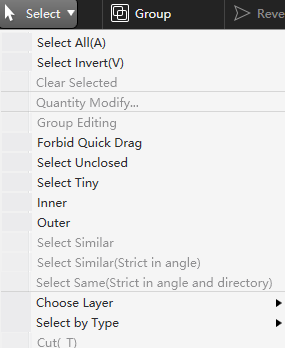

Select All: Select all graphics.
Select Invert: Select unselected graphics.
Clear Selected: No selection at all.
Select Unclosed: Select all unclosed graphics in the tool path file.
Select Tiny: In the pop-up dialog box, input the X, Y size range of the graphics to be selected, and the system will automatically select the graphics within the size range.
Select by Inner: Select the included graphics.
Select by Outer: Select the not included graphics.
Select Similar: After manually selecting a graphic, click Select Similar, and the system will automatically select the graphic with the same type and size as the selected graphic.
Note
This operation does not strict in angles.
Select Similar(Strict in Angle):After manually selecting a graphic, click Select Similar(Strict in Angle), and the system will automatically select the graphic with the same type and size as the selected graphic.
Note
This operation strict in angles.
More advanced selection operations:
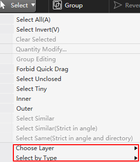

Select by Layer: Select the corresponding layer in the submenu, and the system will automatically select the graphics in this layer.
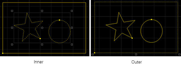
Select by Inner-outer: In the submenu, select the corresponding inner layer graphics (included graphics) or outer layer graphics (not included graphics). The system automatically selects the graphics corresponding to the nesting relationship, and the effect diagram is as follows:
Select by Type: Select the corresponding graphic type in the submenu, and the system will automatically select the same type of graphic.
Basic Operation
Commonly used basic operations include:
- Cut (Ctrl+X)
- Copy (Ctrl+C)
- Datum copy (Shift+Ctrl+C): Select a point. The relationship between the graphics and the mouse position is the same as that of the datum and the original graphics when pasting.
- Paste (Ctrl+V)
- Paste as group: Copy two or more objects, select to paste as a group, then the selected objects will be combined into a group when pasted.
- Delete
- Clear clipboard
- Clear selected: It can also be realized by click the blank area.
- Forbid quick drag: After checking, it will not allow drag, copy, and rotate graphics to avoid misalignment of graphics due to misoperation.
Transform Graphic
Click  Transf drop down box in the common toolbar, to provides many geometric transformation functions, most of the commonly used geometric transformations only need to click Transf drop down box. Select the target and it can be completed.
Translate
Move objects a certain distance. As a result, the coordinate of objects will be changed without changing the size of objects.
Operation Steps:
- Select the object.
- Select any of the following methods to perform translate:
Hold down the left mouse button and drag the graph.
On the keyboard, press ↑、↓、 ←、 →.
Call translate function:
Click
Transf → Translate in the common toolbar or click Edit → Translate in the menu bar.Left click to select the reference point position.
Left click to select the target position.
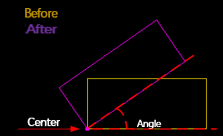
Rotate
Move or turn an object around a certain fixed point, so as to change the position and direction of the object.
Operation Steps:
- Select the object.
- Select any of the following methods to perform rotate:
After entering the rotation angle in the Rotation input box on the common toolbar, press Enter to confirm.
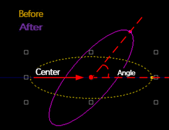
If the object is a rectangle or text, the lower left point of the object is the rotation center:
If the object is a/an star, polygon or ellipse, the center point of the object is the rotation center:
Rotate any angle:
Click
Transf→ Rotate any Angle in the common toolbar or click Edit → Rotate any Angle in the menu bar.Left click to select the center of rotation.
Move the cursor to adjust the rotation angle, left click to confirm. Or enter the angle in the input box of the rotation center and press Enter to confirm.
90° or 180° rotation:
- Click Transf→ Clockwise Rotate 90 / Anticlockwise Rotate 90 / Rotate 180 in the common toolbar or click Edit → Clockwise Rotate 90 / Anticlockwise Rotate 90 / Rotate 180 in the menu bar.
- Click
Mirror
Including vertical and horizontal mirror:
Vertical Mirror: Mirror along X-axis with the center of the object as the center of rotation.
Horizontal Mirror: Mirror along Y-axis with the center of the object as the center of rotation.
After selecting the target object, select the following methods to perform mirror:
Click
Transf → Vertical Mirror / Horizontal Mirror in the common toolbar.Click Edit → Mirror → Vertical Mirror / Horizontal Mirror in the menu bar.
Align
Change the relative position between graphics to align them.
Operation Steps:
Select multiple objects.
Select any of the following methods to perform align:
Click
 Center Point Alignment in the drawing toolbar.
In the menu bar, click Edit → Align , select the alignment method in the submenu:
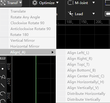
In the common toolbar, click
Transform → Align , select the alignment method in the submenu:- Align Left
- Align Right
- Align Top
- Align Bottom
- Align Center Point
- Align Horizontally
- Align Vertically
- Distribute Horizontally
- Distribute Vertically
System performs alignment automatically.
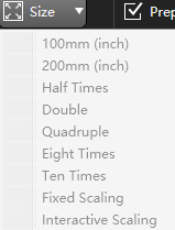
Size Scale
Scale the graphic proportionally and change the size of the graphic. The software provides 7 rapid size scale.
Caution
After modifying the size, the lead out line and kerf compensation will not be transformed at the same time, that is, the value remains unchanged.
Multiple Quick Scale
Operation Steps:
Select the object. In the common toolbar, click Size → select the scale method from the drop down menu.
Accurate Size Scale
Operation Steps:
Select the object.
In the common toolbar, click
 Size → Fixed Scaling, or in the menu bar, click Edit → Scale → Fixed Scaling.
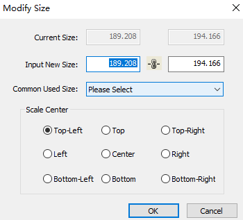
Input size.
- When the lock state in the dialog box is
 , you can select the Command Used Size, and when entering a new size, the length and width will be modified according to the size ratio of the original image.
 - When the lock state in the dialog box is
 , the Command Used Size cannot be selected. When entering a new size, the length and width can be entered separately.
- When the lock state in the dialog box is
Select scale center.
The scale center can specify the positional relationship between the new graphics and the original graphics after scaling. For example, if you select "top left", it means that after scaling, the new graphics and the original graphics are aligned according to the top left corner, and other parts are scaled based on the top left corner.
Interactive Scaling
Operation Steps:
- Select the object.
- In the common toolbar, click Size → Interactive Scaling, or in the menu bar, click Edit → Scale → Interactive Scaling.
- Left click to select the scale center point.
- After left click, move the cursor to adjust the scale ratio.
- Left click to confirm.
Group
Used to form multiple selected objects into a group.
Operation Steps:
- Select multiple objects.
- Select any of the following methods to perform group:
In the common toolbar, click
 Group.
Right click to call the shortcut menu, click Group.
In the menu bar, click Edit → Group/Disband → Group.
The group effect diagram is as follows:
Ungroup
It is used to disband the combined group into multiple graphics.
Operation Steps:
- Select the target group.
- Select any of the following methods to perform ungroup:
In the common toolbar, click
 Ungroup.
Right click to call the shortcut menu, click Break Group.
In the menu bar, click Edit → Group/Disband → Ungroup.
Merge
Merge multiple path objects into a single path object.
Merged objects must meet the following conditions:
- Non-closed object
- Non-dot
- Non-text
- Non-group
Before merging objects, it is suggested to enable catch.
Operation Steps:
Select multiple objects.
Select any of the following methods to open the Join dialog:
In the common toolbar, click
 Optimize → Merge.
Right click to call the shortcut menu, click Join.
In the menu bar, click Edit → Merge.
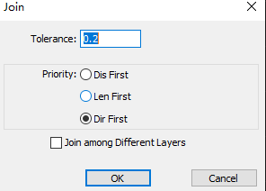
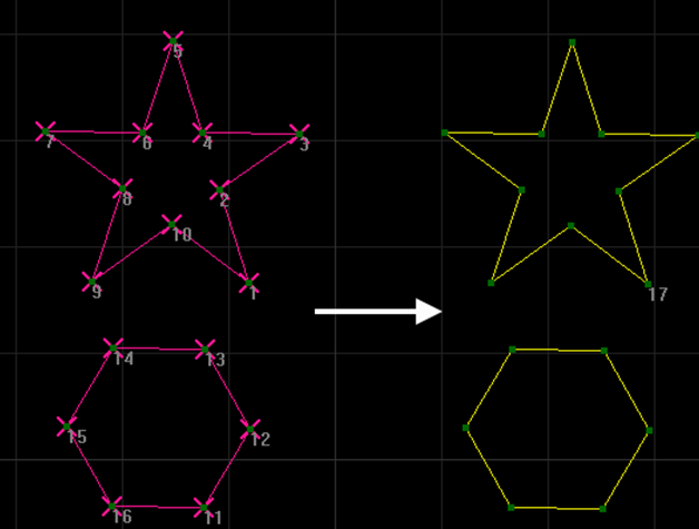
Set the parameters Tolerance and Priority.
Tolerance: The maximum distance between objects that needs to be merged.
Priority: When there are more than three end points satisfying the merge tolerance at the same merge position, the objects with the closest distance, the longest length, and the same direction are preferentially merged.
Optional: Check Join among Different Layers. The system merges objects of different layers into the layer with a higher layer order.
The merge effect diagram of different priority is as follows:

Explode
Delete extra lines to trim the toolpath. It usually applies to polylines.
Use it together with Merge function, to correct mistakes by drawing and make sure machining quality.
According to different machining objects, it can be divided into:
- If the object is a group: Explode objects is equal to Ungroup.
- If the object is text: Explode objects is equal to Convert Text to Graphic.
Operation Steps:
- Select the object.
- Select any of the following methods to perform explode:
In the common toolbar, click
Optimize → Explode.In the menu bar, click Edit → Explode.
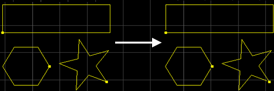
The explode effect diagram is as follows:
Break
It is used to cut objects into several polylines.
It is usually used in the following situations:
- Connect the cutting part to its surrounding material. It equals to micro joint.
- Cut extra objects during drawing objects.
Select any of the following methods to perform break:
- Automatically: To break all the selected objects at the same time, automatically break objects.
- Manually: To break one object each time by freely selecting breaking position, manually break an object.
Automatically
Operation Steps:
Select the object.
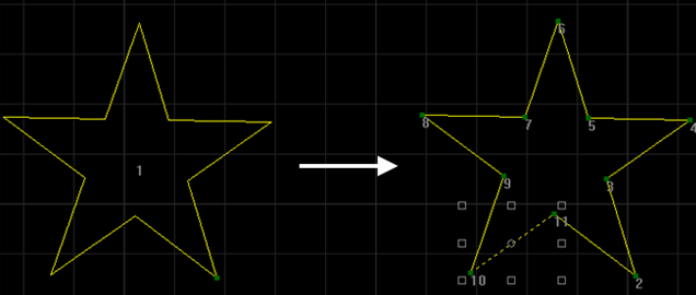
In the menu bar, click Edit → Break to open the Break dialog box:
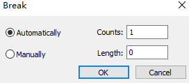
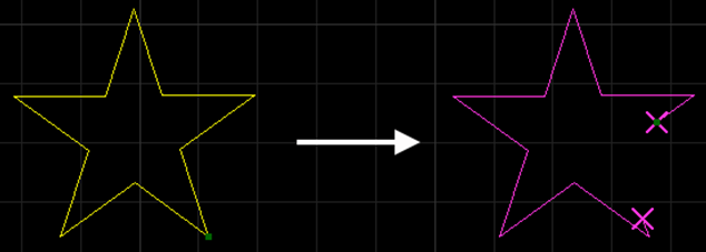
After selecting Automatically, enter the Counts and Length of the break line.
The automatic break effect diagram is as follows:
Manually
Operation Steps:
In the menu bar, click Edit → Break to open the Break dialog box:
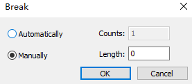
After selecting Manually, enter the Length of the break line.
Click OK, the cursor changes to
 .
.Left click to select the positions for breaking.
Right click to finish breaking.
The mnually break effect diagram is as follows:
Trim
The trim function uses the intersection point as the trim point to delete the selected part.
Operation Steps:
In the menu bar, click Edit → Trim , the cursor changes to
 .
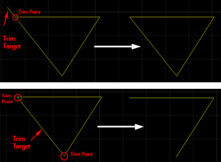
.After selecting the target to be trimmed, left click, the graph will use the intersection point as the trim point, and the selected target will be deleted.
The trim effect diagram is as follows:
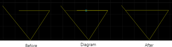
Extend
The extend function is to extend a line to another line to form an intersection, making the line closed. Extend is often applied to unclosed graphics, and does not support line segments without intersection after extend.
Operation Steps:
In the menu bar, click Edit → Extend,
 .
.Move the cursor to the line segment that needs to be extended, and the graphic will display the effect of extend.
Left click to confirm extend.
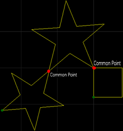
Common Edge
Common edge is used for overlap edges between graphics, so that they share a boundary, which avoids repeated cutting of the same boundary during machining.
The following conditions must be met before common edge:
Closed graphics
Common boundaries are lines or arcs

Graphics with common points
Operation Steps:
Select multiple objects.
Follow any of the following steps to perform common edge:
Select any of the following methods to open the CoEdge dialog box:
Right click to call the shortcut menu, click CoEdge.
In the menu bar, click Tool Path → Common Edge.
In the common toolbar, click the
 CoEdge drop down box → Advanced Settings.
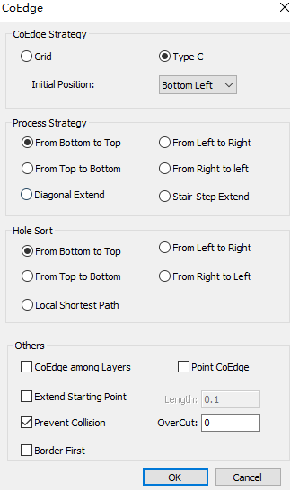
Select CoEdge strategy:
Grid: Cut internal graphics first.
Type C: The tool path is type C cutting graphics.
Optional: If the co-edge strategy is selected as C Type, set the machining order:
From Buttom to Top: According to the order of the center point of each area from bottom to top.
From Left to Right: According to the order of the center point of each area from left to right.
Diagonal Extend: Select the closed area in the lower left corner to start processing. The extend direction is from the lower left corner to the upper right corner.
Stair-Step Extend: Suitable for regular matrix graphics. The machining tool path is stepped, and the extend direction is from the lower left corner to the upper right corner.
Optional: If the CoEdge strategy is selected as C type, single part has inner hole can specify the sorting strategy of the inner hole graphics, that is, set the inner hole sorting:
From Bottom to Top: Machining in the order of the center points of each area from bottom to top.
From Left to Right: Machining in the order of the center points of each area from left to right.
From Top to Bottom: Machining in the order of the center points of each area from top to bottom.
From Right to Left: Machining in the order of the center points of each area from right to left.
Local Shortest Path: The shortest empty path between the cutting of one graphic and the start of cutting of another graphic is the "local shortest path".
Optional: If you need to perform other operations, in the Other area, check the following options:
CoEdge among Layers: Graphics CoEdge between different layers.
Point CoEdge: The graphics contain common points are converted into groups.
Extend Starting Point: to extend the tool path in the opposite machining direction through the start point and turn on the laser in advance, helping completely cut the start point and avoid over-burning. It is applicable to rectangular objects.
Prevent Collision: to avoid colliding with the cutting head after cutting parts in the first region of shared objects. the CoEdge will be cut in the second region.
Note
Only valid for C type CoEdge. Otherwise, maintain the original common edge path, and cut the common edge part when machining the first area.
Over Cut: Over cut strategy.
Border First: The outer frame of the part is preferentially CoEdge.
After the setting is complete, click OK , and the graphics will become a group after CoEdge.