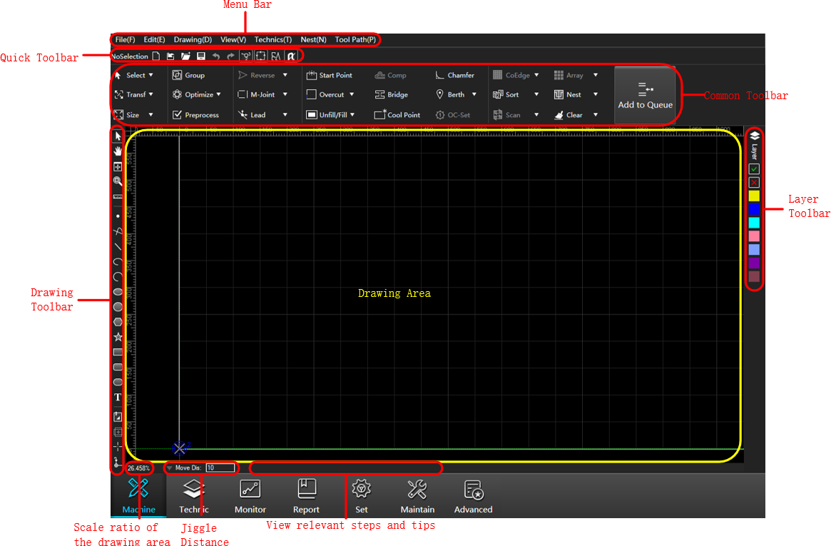
Drawing Interface
The drawing interface is as follows:
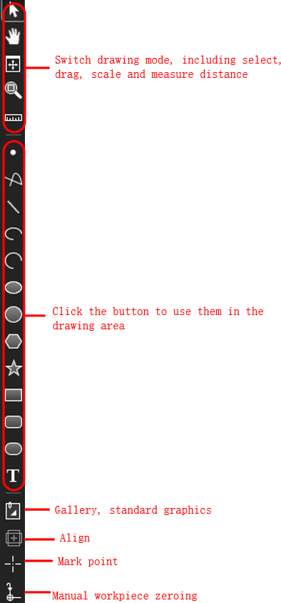
Quick Toolbar
There are three types of displays:
When no object is selected in the drawing area, it is displayed as:

Button Description  New
NewCreate ncex,dxf,dwg,plt,g,ncformat toolpath files. Import
Import dxf,dwg,plt,g,ncformat files. Open
OpenOpen ncexformat files. Save
SaveSave the toolpath file. If to save the newly created tool path file, click to save it as ncexformat file. Undo
UndoUndo the last operation.  Redo
RedoRedo the undo operation.  Show Order
Show or hide machinig order.  Show Direction
Show or hide machinig direction.  Highlight Unclosed Objects
Displays all unclosed graphics with or without a special color (red).  Catch Options
Set the feature items that need to be caught. When any graphic is selected in the drawing area, the information will display:
Select an object:

Select multiple objects:

When calling a drawing tool, displays:

Common Toolbar
Common toolbar is displayed with very prominent icons.
| Button | Description |
|---|---|
 Select Select |
Select all, select invert, clear selected, and select unclosed, select tiny, inner, outer and select similar. For details, please see Automatic Selection. |
 Transform Transform |
Translate, rotate objects, vertically, horizontally mirror and align objects. For details, please see Translate,Rotate,MirrorandAlign. |
 Size Size |
Scale the graphic proportionally to change its size. For details, please see Transform Graphic. |
 Group Group |
Group the selected objects into a group. For details, please see Group. |
 Optimize Optimize |
Perform preprocessing operations on graphics. Include Merge, Explode, Smooth, Curve Segementation, Delete Overlap Line, Delete Tiny, Simplify Curve, Convert Polyline to Cycle, Trim Self-intersection, Convert Text to Graphic. |
 Preprocess Preprocess |
After select single or multiple objects, open the Instant Pre-process dialog box for setting. For details, please see Preprocess. |
 Reverse Reverse |
Set the machining direction. For details, please see Machining Direction. |
 M-joint M-joint |
Reserve a small distance without cutting (reserved notch), so that the workpiece and the plate are connected together. For details, please see M-joint. |
 Lead Lead |
Set machining lead-in and lead-out lines. For details, please see Lead Line. |
 Start Point Start Point |
If there is a lead line, set the start/end point of the lead line; if there is no lead line, set the start point of machining, and start machining the graphic from the selected current point. For details, please see Start Point. |
 Gap Gap |
A seal is formed between the cutting start and end point of the part, and the seal method is divided into gap and overcut. For details, please see Gap. |
 Unfill/Fill Unfill/Fill |
Set unfill and fill. For details, please see Unfill/Fill. |
 Comp Comp |
Compensate the actual machining kerf error. For details, please see Kerf Compensation. |
 Bridge Bridge |
Connect two graphs like a bridge. For details, please see Bridge. |
 Cool Point Cool Point |
Add a cool point at the inflection point of the graphic to improve the cutting effect of the inflection point when cutting thick materials. For details, please see Cool Point. |
 Chamfer Chamfer |
Remove burrs from machining on parts. For details, please see Chamfer. |
 Berth Berth |
Berth the graphic to the workpiece origin. For details, please see Berth. |
 OC-set OC-set |
Set unfill/fill, lead line, machining direction, machining order and kerf compensation at one time. For details, please see OC-set. |
 CoEdge CoEdge |
CoEdge processing is done on the graphics to make them share a boundary. For details, please see CoEdge. |
 Sort Sort |
Specify the machining order of graphics in the tool path file. For details, please see Arrange the Path. |
 Scan Scan |
Find the most efficient path for processing, eliminate the steps of lift and down the tool. For details, please see Scan. |
 Array Array |
Copy and arrange machining graphics in order. For details, please see Array. |
 Nest Nest |
Arrange the machining parts to improve material utilization and machining efficiency. For details, please see Nest. |
 Clear Clear |
Clear the machining track and part of the set machining technology. For details, please see Clear. |
 Add to Queue Add to Queue |
In Nimble mode, save and add the current toolpath to the queue. |
Layer Toolbar
The description of the buttons on the layer toolbar is as follows:
 : Click this button to open the Layer Setting dialog to set the layer technic. For details, please see Layer Technic.
 : Set the selected graphic machining.
 : Set the selected graphics to not be machined, and the graphics will be white at this time.
 : Change the color of the selected object to the color of the corresponding layer.
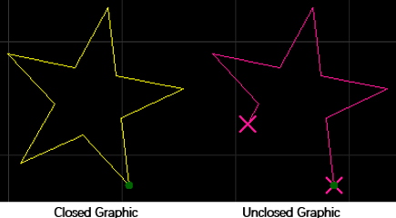
Drawing Area
In the drawing area, you can preview and draw graphics in this area. The types of graphics drawn include closed graphics and unclosed graphics. The schematic diagram is as follows:
Jiggle Distance
View and set the single movement distance of the graphics in the drawing area.
Example: Set the jiggle distance to 10mm, select the graphic and press the → key on the keyboard, and the graphic will move 10 mm to the right.
Drawing Toolbar
Provides basic drawing functions.