Optimize
When importing external graphics, the software can be set to automatically optimize the graphics to achieve better machining results. For details, please see Preprocessing.
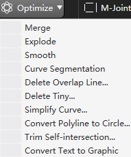
If you need to manually optimize the graphics, you can use the  Optimize button function on the common toolbar. Select the graphics to be processed, click the corresponding button, and operate according to the prompts.
Preprocessing
Automatically process of graphics at once.
Operation Steps:
Select the object.
Select any of the following methods to open the Preprocessing dialog box:
In the common toolbar, click
 Preprocessing.
Right click to call the shortcut menu, click Preprocessing.
In the menu bar, click Edit → Instant Pre-process.
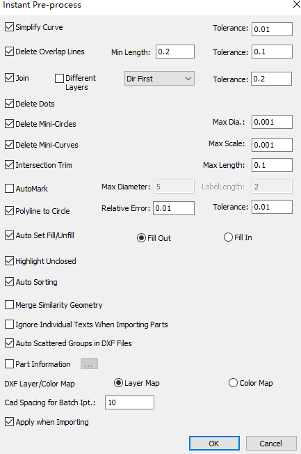
Check the preprocessing item and set the parameter range.
- Simplify Curves
- Delete Overlap Lines
- Merge
- If you need to delete dots, check Delete Dots, and the system will automatically delete dots.
- If you need to delete small circles within the diameter range, check Delete Mini-circles, and set Max Dia., the system will automatically delete small circles within the diameter range.
- If you need to delete small curves within the size range, check Delete Mini-curves, and set Max Scale, the system will automatically delete small curves within the size range.
- Trim Self-intersection
- Convert Polyline to Circle
- Auto Set Fill/Unfill
- Highlight Unclosed
- Auto Sorting
- Part Information: After checking, set the identifier and quantity of the part name. When drawing CAD drawings, you can use the set identifier to set the part information. After importing to the system software, you can quickly obtain the part name and number.
- DXF Layer/Color Map: Set the corresponding relationship between the layer color of the system software and the CAD drawing.
Optional: Check Merge Similarity Geometry , in the menu of imported parts, the same parts will only be displayed once in the parts list, and the number will be superimposed, and not all will be expanded.
Optional: Check Apply when Importing. The system processes the objects automatically according to the selections above after importing a toolpath file.
Smooth
Smooth processing is performed on multi-segment polyline graphics, and the processed graphics are smoother to ensure smooth processing.
Operation Steps:
Select the object.
Select any of the following methods to perform smooth curves:
In the common toolbar, click
Optimize → Smooth.Right click to call shortcut menu, click Smooth.
In the menu bar, click Edit → Smooth.
After smoothing curves, the prompt Curve Smoothing Successful shows.
Curve Segmentation
It is used to cut off the graphics and break the lines of the graphics.
Common usage scenarios are as follows:
Through break processing, the cut parts are connected with the surrounding materials, which is the same as micro joint.
Cut redundant graphics in the graphics drawing stage, which is convenient for cutting out ideal shapes.
The difference between curve split and Break:
The difference in the method: split can only select the break point manually, and the break supports automatic and manual selection of the break point.
The length of the break point: the split cannot be set, and the break supports setting the length of the break point.
Operation Steps:
Select any of the following methods to enable curve segmentation:
In the common toolbar, click
Optimize → Curve Segmentation.Right click to call shortcut menu, click Curve Segmentation.
In the menu bar, click Edit → Curve Segmentation.
At this point the cursor changes to
 . At the position of the break point, left click.
The segmentation effect diagram is as follows:
Delete Overlap Line
To delete overlap lines needs to meet the following conditions:
Two graphics that coincide exactly:

Lines that overlap between lines and graphics:
Lines where the graphic overlaps itself:
Operation Steps:
Select multiple objects.
Select any of the following methods to open the Delete Overlap Lines dialog box:
- In the common toolbar, click Optimize → Delete Overlap Lines.
- Right click to call shortcut menu, click Delete Overlap Lines.
- In the menu bar, click Edit → Delete Overlap Lines.
- In the common toolbar, click
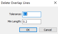
Set the following parameters:
Tolerance: To delete overlap lines, the distance between two lines must be within the maximum tolerance range.
Min Length: To delete overlap lines, the overlap length of the two lines must be greater than the minimum length.
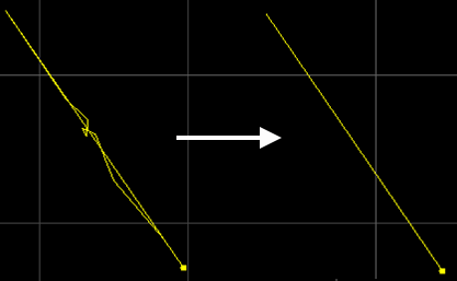
The effect of delete overlap lines is as follows:
Delete Tiny
It can automatically delete dots, tiny circles and tiny curves according to the set conditions. The size of the tiny circles and tiny curves to be deleted can be set.
Operation Steps:
Select the object.
Select any of the following methods to open the Delete Tiny Objects dialog box:
- In the common toolbar, click Optimize → Delete Tiny.
- In the menu bar, click Edit → Delete Tiny.
- In the common toolbar, click
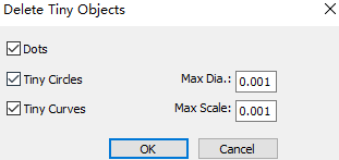
Select the item to be deleted and set the size.
Click OK, and a prompt box will pop up indicating the number of tiny graphics to be deleted.
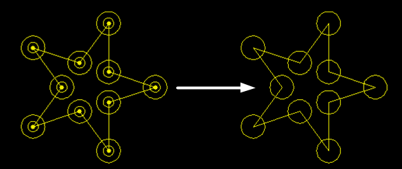
The effect diagram of deleting tiny graphics is as follows:
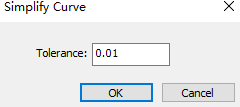
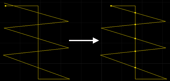
Simplify Curve
It is used to reduce the number of control points for polylines, so as to speed up the response time to object operations.
Control points are special points that control and adjust the shape of a curve.
Operation Steps:
Select the object.
Select any of the following methods to open the Simplify Curve dialog box:
- In the common toolbar, click Optimize → Simplify Curve.
- In the menu bar, click Edit → Simplify Curve.
- In the common toolbar, click
Set the tolerance and click OK.
The system automatically reduces the number of control points for polylines within the set tolerance.
Convert Polyline to Circle
It is used to turn closed polylines shaped like circles into circles.
Operation Steps:
Select the object.
Select any of the following methods to open the Convert Polyline to Circle dialog box:
In the common toolbar, click
Optimize → Convert Polyline to Circle.Right click to call shortcut menu, click Convert Polyline to Circle.
In the menu bar, click Edit → Polyline to Circle.
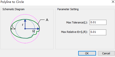
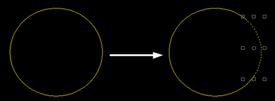
According to the schematic diagram, set parameters max tolerance and max relative error.
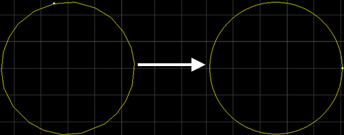
After successfully turning polylines into circles, the following dialog box pops up. The result is as follows:
Trim Self-intersection
Separate the self-intersecting polyline graphics and cut off redundant lines.
Operation Steps:
Select the object.
Select any of the following methods to open the Intersection Trim dialog box:
In the common toolbar, click
Optimize → Trim Self-intersection.In the menu bar, click Edit → Trim Self-intersection.
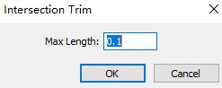
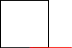
Set the length, click OK, the software will automatically cut off the lines within the length range.
The self-intersecting trim effect diagram is as follows:
Convert Text to Graphic
Convert text to polylines to ensure that technic can be added later.
Operation Steps:
Select the object.
Select any of the following methods to perform convert text to graphic:
In the common toolbar, click
Optimize → Convert Text to Graphic.Right click to call shortcut menu, click Text to Polylines.
In the menu bar, click Edit → Convert Text to Graphic.