Kerf Compensation
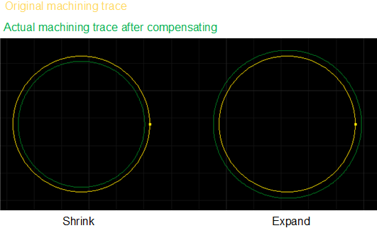
Laser cutting has a kerf (the part that is lost during cutting), which makes the size of the actual cut part deviate from the theoretical size of the part. This operation enables geometric compensation for deviations.
Kerf compensation types are divided into:
All Shrink: Shrink the cutting area for all selected parts.
All Expand: Expand the cutting area for all selected parts.
Unfill: Shrink; Fill: Expand: shrink the cutting area for parts with unfill attribute, and expand the cutting area for parts with fill attribute.
Prerequisite:
Before setting kerf compensation, make sure the following:
The text has been turned into polylines. See Convert Text to Graphic.
Non-dot, scan, self-intersecting, CoEdge graphics.
Closed graphics.
Operation Steps:
Select one or more graphics.
Select any of the following methods to open the Kerf Compensation dialog box:
In the common toolbar, click
 Comp.
Comp.In the menu bar, click Technics → Kerf Compensation.
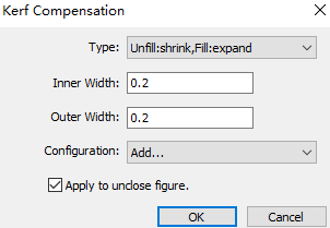
Set the compensation type.
Set the inner and outer width.
Check Apply to Unclose Figure as required.
Click OK.
The result of kerf compensation is as follows:
Related Tasks:
If you need to save the commonly used inner/outer width for direct call next time:
Select Add in the Configuration drop down box, and the Configuration dialog box will pop up:
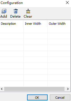
Click Add, set the name in the Description column, and set the inner and outer widths in the Inner Width and Outer Width columns respectively.
When you need to use it, select the name set in the Description column in the Configuration drop down box, and the system will automatically fill in the inner width and outer width.