Layer
Overview
As a core function, layer function is used to set technics for different layers.
You can select one of the following to open Layer Setting dialog box:
In the layer toolbar, click
 .
.In the menu bar, click Technics → Layer Setting.
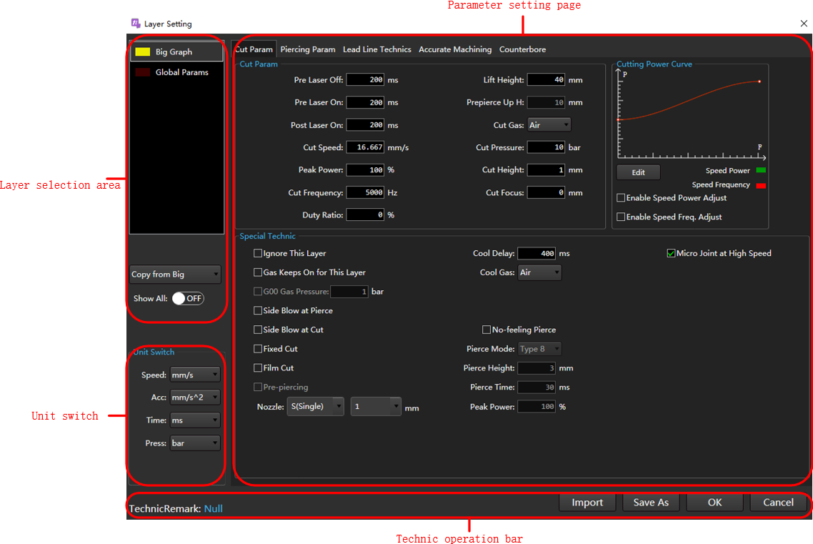
The Layer Setting dialog box is as follows:
| Name | Description |
|---|---|
| Layer selection area | The system offers 7 layers with different colors. You can set technics for each layer, and the system regards objects with the same color as the same layer and sharing the same technics. ▪ Copy from XX: You can copy and apply the layer parameters to the target layer. ▪ Set Show All to ON status: The system displays all layers; otherwise , the system only shows layers in the current tool path file. |
| Parameter setting page | Click the switch button in the page to switch to the corresponding parameter setting page. |
| Technic operation bar | Available operations: save as, import, save or cancel the modification of the current layer parameters. |
| Unit switch | Unit of switch parameter. |
Operation
The operations aim to set related parameters for the target layer.
Operation Steps:
Select any of the following methods to open the Layer Setting dialog:
In the layer toolbar, click the
.In the menu bar, click Technics → Layer Setting.
(Optional) If the target technic file needs to be imported from the technic library, perform the import technic operation. For details, please see Import.
In the Layer Selection Area click the layer to be set.
(Optional) If the currently set layer parameters are similar to other layers, select a layer in the "Copy from XX" drop down box, copy and apply the layer parameters to the target layer.
Note
When performing this operation, there must be multiple layers in the current tool path.
(Optional) In the Unit Switch area, switch the unit of the parameter as needed.
In the Parameter Setting Page area, set the technic parameters, and the parameter descriptions are as follows:
After setting the parameters, repeat steps 3 ~ 6 as needed to set the parameters of the next layer.
(Optional) If need saves the current technic to the technic library, execute the save technic operation. For details, please see Import.
Click OK to close the Layer Setting dialog box to complete the layer technic setting.
Import
Import the target technic file from the technic library, that is, quickly apply the layer technic parameter information to the software.
Operation Steps:
In the Layer Settings dialog box, click Import, in the Import dialog box, click the technic to be imported and make it highlight.
Click OK, a confirmation prompt box will pop up, click OK.
Add Technic Remark
It is used to set technic remarks, and it is convenient to automatically generate the name of a technic file during saving or saving as the technic file.
Naming rule: Laser power-Material-Thickness-Mach type-Cutting gas-Nozzle type-Aperture-Remarks
Operation Steps:
In the Layer Setting dialog box, click the blue text after Technic Remark, and the Technic Info dialog box will pop up:
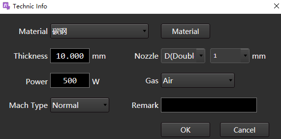
Set relevant parameters according to the actual situation and add notes.
Where there are no suitable options for Material and Nozzle, please refer to Manage Material, Manage Nozzle Information add Material and Nozzle.
Click OK.
Save As
Save the current technic to the technic library.
Naming rule: Layer name-Material-Thickness-Laser power-Mach type-Nozzle type-Aperture-Cutting gas-Remarks
Operation Steps:
In the Layer Setting dialog box, click Save As to open the Save Technic As dialog box.
Set relevant parameters according to the actual situation and add notes.
Click OK.
Parameter Description
Cut Param
It is used to set cutting parameters, special technic and edit power curve.
Used to make the cutting power and frequency change with the cutting speed accordingly and make sure thermal power absorbed in unit area is the same and achieve fine cutting result, so as to solve problems like over-burning around the corner and different cutting results in terms of thickness.
Cut Param area. The parameters are described as follows:
Parameter Description Pre laser off Delay before turning off the laser. Pre laser on Delay before turning on the laser. Post laser on After turning on the laser and continuing to set the time, go to the next step. Cut speed The actual cutting target speed. Peak power Adjust the laser through the analog quantity to set the laser intensity during cutting. Cut frequency When cutting the carrier frequency of the PWM modulation signal is also the number of times the light is emitted within one second. The larger the value, the more continuous the light is emitted. Duty ratio Adjust the laser through PWM to set the duty ratio when cutting. Lift height When switching cutting graphics, the height of the laser head lifting. Prepierce up H During the prepiercing process, each time one hole is pierced, the cutting head is lifted up. If the total number of piercings in the tool path is 1, this parameter will not take effect. Cut gas The type of assist gas used while cutting. Cut pressure The pressure of the auxiliary gas during cutting needs to be used in conjunction with a proportional valve. Cut height The height of the nozzle from the plate when cutting. If the height value set by the parameter is less than the maximum height of direct follow, it will follow directly to this position. If the parameter setting height is greater than the maximum height of direct following, the Z-axis will first follow to the position 1mm away from the board surface, and then move to the height value set by the parameter incrementally based on this. Cut focus Takes effect when focus control is enabled. The position of the focal point when cutting. Special Technic area. The parameters are described as follows:
Parameter Description Ignore this layer Not machining all graphics in the current layer. Gas keep on for this layer Do not close the blowing port during machining the graphics in this layer. Side blow at pierce When piercing, open the side blow port. Side blow at cut When cutting, open the side blow port. Fixed cut Whether to enable fixed height cutting. That is, when cutting, whether to maintain the fixed Z-axis coordinates for cutting. Film cut Enabled when cutting metal materials with surface coatings. Pre-piercing All machining objects in the current layer enable the pre-piercing function, so that all tool paths are perforated in advance before actual machining. Nozzle Type and size of nozzle. Micro joint at high speed The laser is not turned on at the micro joint, and the cutting head continues to move without deceleration. Cool delay When machining to the cooling point, the time for blow cooling. Cool gas The gas used for blow cooling. No-feeling pierce Enable no-feeling pierce.
Note: no-feeling pierce and the actions of level one to five level piercing are mutually exclusive, that is, if No-feeling Pierce is checked, the parameters in the Piercing Param page cannot be set.
The system automatically performs the following machining actions:
1. Enable follow-up valve and blow valve.
2. Control the cutting head to move to the height of no-feeling pierece.
3. Turn on the laser valve to start no-feeling pierece, and the duration is the no-feeling pierece time.Pierce mode Types 1-10 correspond to 10%-100% duty ratio respectively. Pierce height The height of the nozzle from the plate when no-feeling piercing. Pierce time The light emission time of the current piercing stage. In the power curve area, check Enable Speed Power Adjust and Enable Speed Freq. Adjust as required. The parameters are described as follows:
Parameter Description Enable Speed Power Adjust When cutting, the cutting power changes with the cutting speed, and the specific value is determined by the speed power curve. Enable Speed Freq. Adjust When cutting, the cutting frequency changes with the cutting speed, and the specific value is determined by the speed frequency curve.
Click Edit to pop up the Speed Power Curve Editing dialog box:
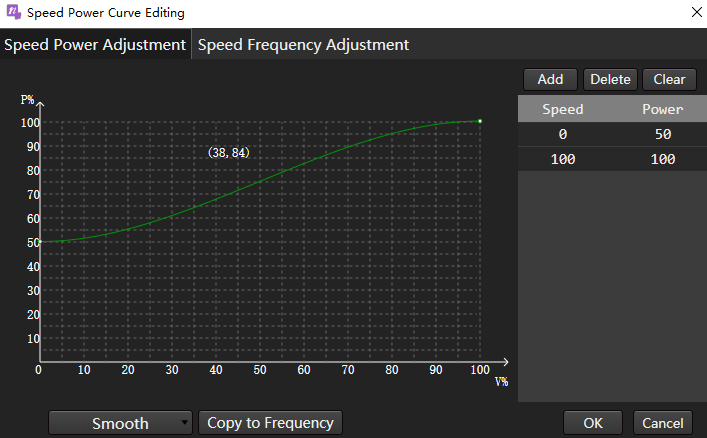
Select any of the following methods to edit the power curve, taking Enable Speed Power Adjust as an example:
Edit in curve box:
Double click the target position to add a curve node.
The more nodes added, the more accurate the curve.
Double click the added node position to delete the curve node.
The list on the right adds or deletes the corresponding speed and power values synchronously.
In list editor:
Click Add, and set of speed and power values will be automatically added to the list. After double clicking to modify the value, click the blank area.
Caution
The speed power curve is an incremental curve, and the added values need to be increased sequentially and 0 and 100 cannot be modified.
Select a group of speed and power values, and click Delete to delete this group of values.
The left curve box synchronously adds or deletes the corresponding nodes.
To restore the curve to the default curve, click Clear.
During machining, the system will automatically adjust the speed and power/frequency matching relationship according to this curve, without other manual operations.
Piercing Param
It is used to select the piercing method and set the piercing parameters.
The piercing method description is as follows:
Parameter Description None The system automatically performs the following machining actions:
1. Enable the follow-up valve and blow valve.
2. After controlling the cutting head G00 to descend to Cutting Height, wait for the Blow Delay time set in Common Parameter.
3. Turn on the laser valve and start cutting.1st Seg./2nd Seg. The system automatically performs the following machining actions:
1. Enable the follow-up valve and blow valve.
2. After controlling the cutting head G00 to descend to Pierce Height, wait for Blow Delay time.
3. Turn on the laser valve and start piercing for Pierce Delay.
4. According to the piercing method, do the following:
▪ Gradual: Do not turn off the laser valve, go down to Cutting Height at Increment S, and start cutting.
▪ Segment: Turn off the laser valve, control the cutting head G00 to descend to Cutting Height, turn on the laser valve, and start cutting.
▪ Frequency Conversion: Do not turn off the laser valve. First, within the frequency conversion time, the frequency conversion pierce machining is gradually changed from the start frequency, duty ratio → end frequency, and duty ratio of frequency conversion piercing. Then, within the pierce light output delay time, constant pierce machining is pierced with the stop frequency and duty ratio.3rd Seg. The system automatically performs the following machining actions:
1. Perform 3rd piercing.
2. Perform 2nd piercing.
3. Perform 1st piercing.4th Seg. Commonly used for thick plate piercing. The system automatically performs the following machining actions:
1. Perform 4th piercing.
2. Perform 3rd piercing.
3. Perform 2nd piercing.
4. Perform 1st piercing.5th Seg. Commonly used for thick plate piercing. The system automatically performs the following machining actions:
1. Perform 5th piercing.
2. Perform 4th piercing.
3. Perform 3rd piercing.
4. Perform 2nd piercing.
5. Perform 1st piercing.The parameters related to setting piercing are described as follows:
If need to copy the left/right piercing parameters, click
 /
/ to copy.
Parameter Description Increment S Sets the speed from pierce height fall to cutting height using increment piercing. Peak power Adjust the laser through the analog quantity, and set the laser intensity when piercing. Frequency The carrier frequency of the PWM modulation signal is used for pierce, and a lower frequency is generally used for pierce, and pulse pierce is used to avoid blast hole. Duty ratio Adjust the laser through PWM to set the duty ratio during piercing. Gas Auxiliary gas used during piercing. Press The pressure of the auxiliary gas during piercing needs to be used in conjunction with the proportional valve. Height The height of the piercing position from the tube. Focus Effective after enabling focus control. The position of the focal point during piercing. Punch delay The time when laser is turned on at the piercing height during gradual piercing and segment piercing. Extra blow Extra blow function switch:
▪ Switch to ON: Turn off the laser to perform blowing.
▪ Switch to OFF: There is no extra blow after the pierce is completed.Extra blow height The height of the extra blow.
If the height value set by the parameter is less than the maximum height followed directly, it will follow directly to that position.
If the height value set by the parameter is greater than the maximum height directly followed, the Z-axis first follows to a position 1mm away from the board surface, and then uses this as a reference increment to move to the height value set by the parameter.Extra blow gas Air, nitrogen, oxygen. Extra blow pressure The pressure value during blowing. Blow time The interval time for blowing after turning off the laser.
Lead Line Technics
Used to select the lead method and set lead parameters.
Select the lead method, the lead method is described as follows:
Lead Method Description Lead line technic Since the lead fall slowly lifts the height of the pierce, parameters such as the power of the lead need to be increased accordingly to ensure that the pierce can penetrate. Fall slowly In the initial stage, the slow speed leads to high energy, and the large amount of slag can easily cause jitter with the movement. The influence of slag on the capacitance can be reduced by raising the cutting head to the height of the lead. Circle In order to remove the area with excessive slag, but it is not necessary to consider the cutting effect. According to the selected lead method, set the corresponding parameters. The parameters are described as follows:
Parameter Description Cut speed The actual cutting target speed. Peak power Adjust the laser through the analog quantity, set the peak current during technic cutting, and correspond to the peak power during technic cutting. Cut frequency The carrier frequency of the PWM modulation signal during technic cutting, that is, the number of times the light is emitted within one second. Duty cycle The duty cycle of technic cutting. Lead line height The position where the Z-axis starts to fall slowly. Stable distance ▪ The distance for lead line cutting at cutting height.
Calculation formula: stable distance = lead length - fall slowly distance.
▪ When the set value is greater than the length of the lead line.
Calculation formula: stable distance = lead length - 3mm.Speed The cutting speed of the lead circle.
Accurate Machining
Set the slowly start and stop technics.
| Parameter | Description |
|---|---|
| Enabled slowly start | Used when poor cutting occurs during the initial stage of thick plate cutting. If fine adjustment is not enabled, the effect is equivalent to the original slow start. |
| Enabled slowly stop | Used when dragging the end stage of thick plate cutting elements. If fine adjustment is not enabled, the effect is equivalent to the original speed. |
| Sharp corner | Used when the corners of the primitives are sharp and easy to burn. Peak power, frequency, duty cycle used to cut sharp corners in and out for a short distance. ▪ Angle: The maximum angle of a sharp corner between line and line/line and arc/arc and arc. ▪ Length: The length of the sharp corner deceleration section and the length of the sharp corner acceleration section (refer to the length of a single end, not the sum of lengths). |
| Arc corner | It is used when the corner of the primitive is an arc and there is dross. For primitives whose curvature radius is less than or equal to the set radius in the graphic, the peak power, duty cycle and frequency can be set independently. |
| Accurate cutting | It is used when high power machine thin plate cutting (when the auxiliary gas is high pressure gas such as nitrogen and air) corners hang slag. |
Finely adjust the technic at the start and end of cutting to improve problems such as burn through, impermeable cut or over burned slag.
Caution
The slowly start and stop technic conflicts with the following three machining technics.
- During fly cutting and high-speed micro-joint, the slowly start and stop technic does not take effect.
- When lead fall slowly takes effect, slowly start technic does not take effect.
- When the slowly start and stop technic is in effect, the speed power regulation is not in effect.
Counterbore
Through the counterbore technic function, the section effect of the precious metal can be guaranteed, and the counterbore can be directly machined to avoid drilling and chamfering.
This technic is only supported in large graphics/medium graphics/small graphics/L1/L2/L3 layers, not in marking and global parameter layers.
Click Copy Cut Param to copy the parameters in the Counterbore Process Param page of the layer to the counterbore technic, and a dialog box will pop up for confirmation after click.
- Process Param area, the parameter description is as follows:
| Parameter | Range | Unit | Description |
|---|---|---|---|
| Pre laser off | [-10000, 1800000] |
ms | The counterbore auxiliary line machining is finished. The delay waiting time before turning off the light, a negative number means turning off the light in advance. |
| Pre laser on | [0, 1800000] |
ms | The machining of the counterbore auxiliary line starts, and the delay waiting time before lighting. |
| Post laser on | [0, 1800000] |
ms | The machining of the counterbore auxiliary line starts, and the delay waiting time after lighting. |
| Cut speed | [10, Maximum machining speed] |
mm/min | The machining speed of the counterbore auxiliary line, the maximum machining speed is: the sum speed of the maximum speed of X, Y single axis. |
| Peak power | [0, 100] |
% | Laser peak power during counterbore auxiliary line machining. |
| Cut frequency | [0, 65535] |
Hz | The PWM frequency of the laser during the machining of the counterbore auxiliary line. |
| Duty ratio | [0, 100] |
% | The laser PWM duty cycle during the machining of the counterbore auxiliary line. |
| Lift height | [0, 1000] |
mm | The lifting height of the laser head when machining the counterbore auxiliary line. |
| Cut gas | 1.Air, 2.Nitrogen, 3.Oxygen | - | The type of blowing gas used in counterbore auxiliary line machining, the actual gas type can be configured. |
| Cut pressure | [0, Gas maximum pressure] |
bar | The blowing pressure of the counterbore auxiliary line machining, the maximum pressure of each type of gas can be configured. |
| Cut height | [0.01, 100] |
mm | The height from the plate when the counterbore auxiliary line is machined. |
| Cut focus | [W-axis negative soft limit, W-axis positive soft limit] |
mm | It is the focus position when machining the counterbore auxiliary line, and it is invalid when the focus control is not enabled. |
- Special Technic area, the parameters are described as follows:
Counterbore technic special technic only supports: fixed cut, side blow at cut.
- When fixed cut is enabled, the Z-axis moves to the position Cut Height away from the board, and then the Z-axis keeps cutting at the same height.
- Enable side blow at cut, open the side blowing port before machining the counterbore auxiliary line, and close the side blowing port after the counterbore auxiliary line is machined.
Layer Application
When drawing a part, the layer technic without machining is used by default, that is, the white layer. This section describes how to add layer technic to a part.
Operation Steps:
In the drawing area, select a graphic or part.
In the layer technic area, click the color of the layer, that is, the color of the selected object becomes the corresponding layer technic color.