Lead Line
Set the lead line in the waste area to avoid machining errors or workpiece damage caused by the laser staying at the start point for a long time at the beginning of machining. Make machining more precise.
The types of lead line:
Lead-in: Including line, arc and hook type, the hook type is formed by connecting arc and line.
Lead-out: Including line and arc type.
The selection of the lead line type is determined by the cutting technic. According to the actual situation, set relevant parameters such as Speed, Lead Line Height on the Lead Line Technics page of Layer.
Automatically Set Lead Line
Automatically add lead lines to the selected object according to the set value.
Operation Steps:
Select one or more objects.
Select any of the following methods to open the Lead Line dialog box:
In the common toolbar, click
 Lead.
Lead.Right click to call the shortcut menu, click Lead Line → Set.
In the menu bar, click Technics → Lead Line → Set.

In the Lead-in and Lead-out areas, set relevant parameters. The parameter descriptions are as follows:
Parameter Description Type Including line, arc and hook type, where the hook type is composed of arc and line. Angle ▪ The angle of line type lead line refers to the angle between the lead line and the tangent line at the intersection point of the primitive.
▪ The angle of the arc type lead line refers to the central angle.Length ▪ The length of line and arc type lead line refers to the length of line and arc.
▪ The length of the hook type lead line refers to the sum of the radius of the arc part and the length of the line part.Radius The radius of the hook type lead line is the radius of the arc part of the lead line. Add tiny circle in start point In order to solve the problem that the accumulation of slag affects the cutting effect when piercing thick plates. Adding a suitable small round hole at the starting point of the lead line can cut off the slag at the same time, so as to ensure the cutting quality. Circle radius The radius of the tiny circle at the start point of the lead line. Optional: If it is a closed graphic, set the following parameters in the Seal area:
Gap: Unclosed lead line means not cutting.
Over: Seal lead line.
In the menu bar, click Technics → Lead Line → Seal → Gap/Over to edit or delete the gap and overcut separately.
Select any of the following methods to set the lead line position:
If select Automatic Lead Position, select as needed:
Corner First: Prioritize adding lead lines at corners.
Edge First: Add lead lines on the longest edge first.
If select Set by Total Length(0~100), set the percentage of the total side length of the graphic from the start point of machining to the position of the lead line.
Only applies to closed graphics.
In the Advanced Options area, select as desired:
Retain Position, Change Leads Type
Retain Leads Type, Change Position
Close only
Auto Set Fill/Unfill
Fill only
Unfill only
Check Lead-in/out Line: If Check Lead-in/out Line is checked, the software will automatically check whether the lead line is reasonable, and if it is reasonable, a dialog box will pop up and display "Check lead line passed".
Click OK.
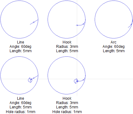
The effect diagram of the lead line is as follows:
Manually Set Lead Line
Use the mouse to specify the position of the lead line, and add the lead line according to the set value.
Operation Steps:
Select one or more objects.
Select any of the following methods to open the Leader Line dialog box:
In the common toolbar, click
Lead.Right click to call the shortcut menu, click Lead Line → Set.
In the menu bar, click Technics → Lead Line → Set.
In Lead-in , Lead-out and Seal areas, set relevant parameters. For details, please see Automatically Set Lead Line.
In the Position area, click Set by Mouse to return to the drawing area, and the cursor changes to
 .
.Click the graphic boundary to manually specify the position of the lead line.
After setting, right click or press Esc key to exit the tool.
Modify Lead Line
Manually modify the position of the lead line.
Operation Steps:
Select any of the following methods to call the function of manually setting the start point:
In the common toolbar, click
 Start Point.
Select any object, right click to call the shortcut menu, click Lead Line → Start Point.
In the menu bar, click Technics → Lead Line → Set Start Point.
As needed, do the following:
Left click on the graphic boundary.
Only modify the position of the lead line, not modify the angle and length.
After left clicking outside the graphic, left click on the border of the graphic.
Draw a line type lead line from outside the graphic to the graphic.
Right click or press the ESC key to exit the start point function.
Check Lead Line
Check whether the lead line is reasonable, if not, give a modification suggestion and modify it automatically.
Operation Steps:
Select one or more graphics.
In the common toolbar, click
Lead Line → Check the Lead Line.
Result:
- If there is an unreasonable lead line, it will be modified automatically.
- If the system cannot automatically modify the unreasonable lead line, a prompt box will pop up.