Micro Joint
It is used to connect the cutting part with surrounding material without falling down the material. By doing this, you can avoid the problem that the part becomes warped and collides with the cutting head moving at high speed, because the cutting part can neither fall from the gap of supporting rods nor be held by the supporting rods.
Automatic Micro Joint
Automatically add micro joints to the selected objects according to the set value.
Operation Steps:
Select the object.
Select any of the following methods to open the Micro Joint dialog box:
In the common toolbar, click
 Micro Joint drop down box → Automatic Micro Joint.
In the menu bar, click Technics → Micro Joint → Micro Joint.
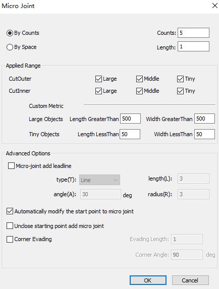
Select by counts or by space micro joint. The system automatically performs micro joint on the selected objects according to the set value.
In the Applied Range area, set the size of the large and small graphics. Check the graphic range of the micro joint.
In the Advanced Options area, check the options as required:
Micro joint add lead line, set the lead line parameters after checking
Automatically modify the start point to micro joint
Unclose starting point add micro joint
Corner evading, set the following parameters after checking, otherwise all points support micro joint.
- Evading Length: Range: 0.001mm~10mm
- Corner Angle: Range: 90°~180°
After setting, click OK, the system will automatically add micro joint according to the set value.
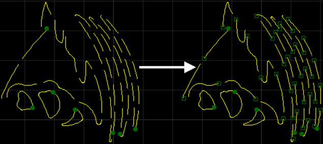
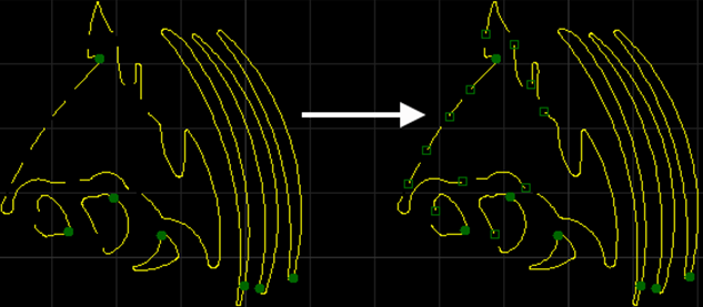
When By Counts is selected and the number is set to 2. The before and after effects of automatic micro joint are as follows:

If need to view the position of the added micro joint more clearly, in the menu bar, click View → Show Micro Joint, the effect picture is as follows:
Manual Micro Joint
Select the micro joint position. When setting manually, it is recommended to enable the catch function.
Operation Steps:
Do not need to select the object, select any of the following methods to open the Manual Micro Joint dialog box:
In the common toolbar, click
Micro Joint.In the menu bar, click Technics → Micro Joint → Manual Joint.
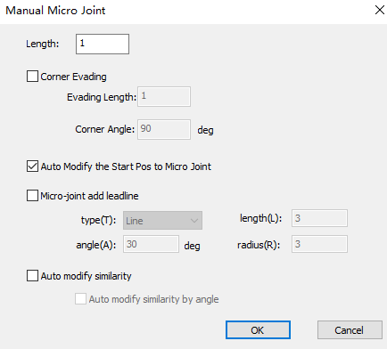
Set the line length.
Check Corner Evading, and set the following parameters, otherwise all points support micro joint.
- Evading Length: Range: 0.001mm~10mm
- Corner Angle: Range:90°~180°
Check options as needed:
- Auto modify the start pos to micro joint
- Micro joint add lead line, and set the lead line parameters after checking it
Click OK. The cursor turns to
 .
.Left click to select the micro joint position.
Right click to exit the manual micro joint function.
The effect diagram of manual micro joint is as follows:
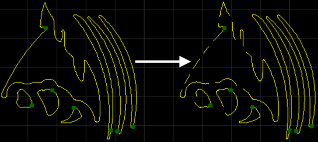
If need to view the position of the added micro joint more clearly, in the menu bar, click View → Show Micro Joint, the effect picture is as follows:
Explode Micro Joint
If you want to separately modify the part after the micro joint is separated, you can use the Explode Micro Joint function. Through Explode Micro Joint the unclosed graphics after the separation will be regarded as a separate individual to modify.
For example, if you want to add leads to the micro-connection part, you need to Explode Micro Joint first, and then add the leads.
Operation Steps:
Select the object.
Select any of the following methods to perform the explode micro joint operation:
In the common toolbar, click
M Joint drop down box → Explode Micro Joint.In the menu bar, click Technics → Micro Joint → Explode Micro Joint.