Nest
Nest function is used to arrange the given parts on the plate reasonably. The number of optimization parameters are provided for adjustment during layout, such as part space, sheet margin, rotation strategy, rotation angle, efficiency/utilization, etc.
It is based on the principle of part nesting priority and material utility maximization, Nest can achieve the following:
- Nest a kind of parts or several kinds of parts.
- Nest a kind of parts over the whole sheet.
- Preview the nesting effect and analyze nesting results.
- Fill the round holes in the advertisement words.
If you need to generate nest report, you can click Machine Assist in the upper left corner on the Machine page, and click Nest Report in the report area.
Prerequisite:
Before nesting, make sure the USB dongle has been successfully inserted into the host, or imported an authorized file.
Nest Sidebar
In the common toolbar, click  Nest to open/close the Nest Sidebar:
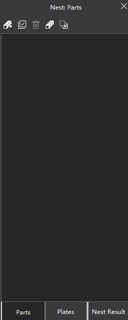
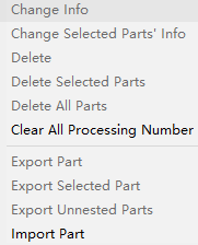
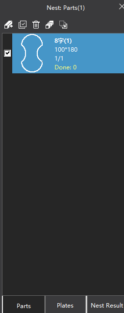
Parts: Display parts as thumbnail.
Click on the part to modify the name, total and machined quantity.
Double click the part to display the part in the drawing area, and it can be modified.
After selecting the part, right click to modify part information, delete, export and import parts.
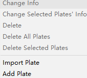
Plates: Display plates as thumbnail.
Click on the part to modify the plate name, total and used quantity.
Double click the plate to display the plate in the drawing area.
After selecting a plate, right click to modify the plate information, delete, export, import, and add rectangular plate.
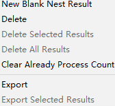
Nest result: Display nest results as thumbnail.
Click the nest result to modify the name and the number of nest machined.
Double click the nest result to display the nest result in the drawing area.
After selecting the nest result, right click to new, delete, and export the nest result.
Part Nest
Nest the parts in the current tool path, and edit the quantity, residual material type and rotation angle of the nested parts.
Before setting nest, make sure that the parts and plates added to the list are closed graphics.
Operation Steps:
Optional: If the parts list does not have the required part, add the part or plate to the parts/plates list:
Select any of the following methods to import parts/plates:
In the common toolbar, click
Nest, click on the pop up Nest Sidebar  Import → Import Part / Import Plate.
In the menu bar, click Nest → Import Part / Import Plate.
Supported part and plate file formats for import include:
dxf,dwg,ncexandlxd.In the drawing area, select the drawn graphics and add:
Right click to cull the shortcut menu, click Add to Part List / Add to Plate List to edit the quantity of parts and plates.
In the menu bar, click Nest → Add to Part List / Add to Plate List to edit the quantity of parts and plates.
After clicking OK, the Nest Sidebar will pop up automatically.
If need to view the added parts or plates, double click the target parts or plates in the list to display them in the drawing area.
Optional: If you need to select the machining part/plate, check the check box in front of the part/plate in the list.
Otherwise all parts/plates in the nest list are defaulted.
Select any of the following options to open the Nest dialog box:
Click
 Nest in the Nest Sidebar.
In the common toolbar, click
NestIn the common toolbar, click
Nest drop down box → Nest.In the menu bar, click Nest → Nest.

In the Part Selection area, select all parts or checked parts in the machining parts list.
Note
If no parts are checked in Nesting Sidebar, the checked parts here are gray and cannot be checked.
In the Plate Selection area, set the plate information.
If you select all the plates in the plate list or check the plates, you can set the material and thickness of the plates.
If you select the standard plate, you can set the width, length, material and thickness of the plate.
In the Nest Parameters area, set the nest parameter information. The parameters are described as follows:
Parameter Description Plate Margin The distance between the part and the edge of the sheet. Part Space Distance between parts. Rotate Strategy The system provides 9 rotation strategies. Among them, the Intelligent Strategy system automatically specifies the optimal rotation angle, and the Specified Angle strategy can freely set the rotate angle. Rotate Angle If Intelligent Strategy or Specified Angle is selected for Rotate Strategy, you can customize the rotate angle. Start Pos Select the top left, bottom left, top right, and bottom right position to start nesting. Direction Select the direction of nest horizontal or vertical. Efficiency/Utilization Slide Efficiency/Utilization to choose to focus on time efficiency or material utilization. Nesting in Part Hole The inner hole belongs to the waste area. To nest a single part into the inner hole of the nested graphics, check Nesting in Part Hole. In the Post-processing area. The parameters are described as follows.
Parameter Description CoEdge: Check CoEdge: and select the CoEdge method, you can click CoEdge Params to view and modify the CoEdge parameters. For details, please see CoEdge. All CoEdge All CoEdges. Only Line CoEdge The sides of the line of the part share the same side, and the sides of the curve do not share the same side. Minimum CoEdge Length Lines smaller than Minimum Coedge Length will not be shared with other lines during nesting. CoEdge Part Number The maximum of several parts are allowed to share edges. Sort After selecting Sort, the results after nesting will be automatically sorted according to the sort strategy set last time. Click Sort Params to view and modify the sort strategy. For details, please see Auto Sort. In the Remnant area, check Generate Remnant. Choose the right remnant type (rectangle, T, L) to maximize material savings.
Optional: Check Clear Previous Nest Results to clear the current nest list and output new nest results.
After the setting is complete, click OK, the system will automatically nest and display the nest results.
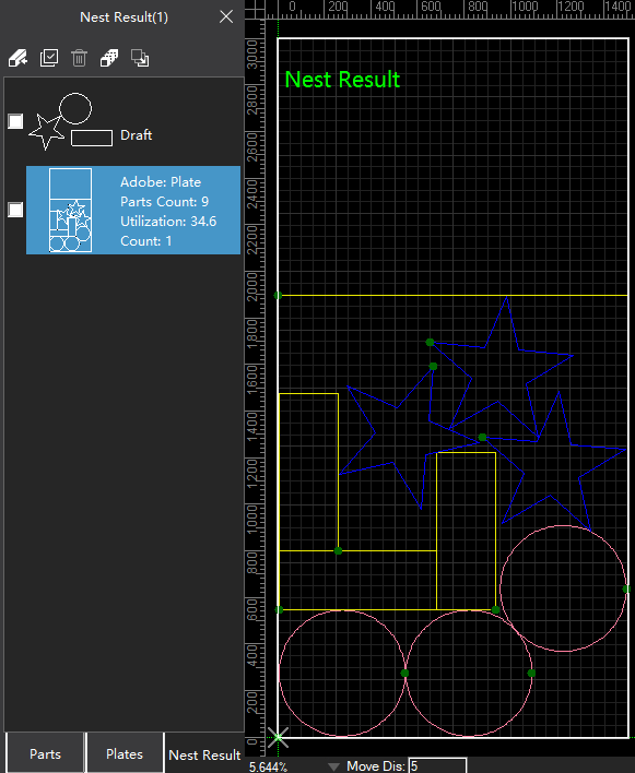
The nest result column in the left shows the number of parts, utilization rate and machined times.
If you need to edit graphics, you can make adjustments in the drawing area.
One Key Nesting
The shortcut for nesting, simplifying the operation steps. Nested parts cannot be edited individually.
Operation Steps:
In the parts list or drawing area, select the target object.
Select any of the following methods to open the Fast One Key Nest dialog box:
In the common toolbar, click
Nest drop down box → One Key Nesting.In the menu bar, click Nest → One Key Nesting.
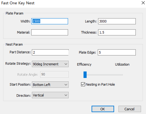
In the Plate Param area, set the width, length, material and thickness of the plate.
In the Nest Param area, set the nest parameter information. The parameters are described as follows:
Parameter Description Plate Margin The distance between the part and the edge of the sheet. Part Space Distance between parts. Rotate Strategy The system provides 9 rotation strategies. Among them, the Intelligent Strategy system automatically specifies the optimal rotation angle, and the Specified Angle strategy can freely set the rotate angle. Rotate Angle If Intelligent Strategy or Specified Angle is selected for Rotate Strategy, you can customize the rotate angle. Start Pos Select the top left, bottom left, top right, and bottom right position to start nesting. Direction Select the direction of nest horizontal or vertical. Efficiency/Utilization Slide Efficiency/Utilization to choose to focus on time efficiency or material utilization. Nesting in Part Hole The inner hole belongs to the waste area. To nest a single part into the inner hole of the nested graphics, check Nesting in Part Hole. After the setting is complete, click OK, the system will automatically make nest and display Nest Result.
If you need to edit graphics, you can make adjustments in the drawing area.
Bestre Nest
It is mainly used for Bestre page cutting of the single graphic. The software quickly covers the entire plate according to the selected parts, set parameters and plate..
Select the graphic in the drawing area.
In the common toolbar, click
Nest drop down box → Bestre Nesting.
In the Plate Param area, set the length and width of the plate.
In the Nest Param area, set the following parameters:
Parameter Description Plate Margin The distance between the part and the edge of the sheet. Part Space Distance between parts. Rotate Strategy The system provides 9 rotation strategies. Among them, the Intelligent Strategy system automatically specifies the optimal rotation angle, and the Specified Angle strategy can freely set the rotate angle. Plate Margin The distance between the part and the edge of the sheet. After the setting is complete, click OK, the system will automatically make nest and display Nest Result.
If you need to edit graphics, you can make adjustments in the drawing area.
Advertise Words Fill
It is commonly used to fill circle holes in advertising board graphics. The circle holes are evenly and orderly arranged in the advertising text.
Circle Fill
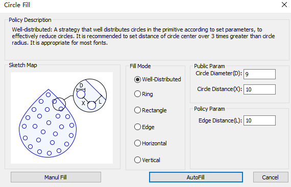
Distribute circle holes evenly in the middle of the element according to the set parameters, and effectively reduce the number of light holes arranged. It is recommended to set the circle spacing to be more than 3 times the circle radius, which is suitable for most fonts.
Operating Steps:
Manual fill
- In the menu bar, click Nest → Advertise Words Fill → Circle Fill, and the Circle Fill dialog box will pop up:
Set Public Param.
Click Manual Fill to automatically close the Circle Fill dialog box, and the cursor changes to
 .
.Note
The small white circle is the circle to be added and the big white circle is automatically generated for helping you to know the circle space.
Click the target position to generate a circle hole.
Right click or press ESC to exit.
Auto fill
Select the object to be filled.
In the menu bar, click Nest → Advertise Words Fill → Circle Fill, and the Circle Fill dialog box will pop up:
Select fill method:
Method Description Well-distributed To well distribute circles in the object so as to effectively reduce circles. It is appropriate for the irregular fonts. Ring To fill circles on generated contour lines so as to orderly arrange filled circles on the contour of the target object and effectively draw contour of object. Rectangle To fill circles with equal intervals, so as to keep intervals between adjacent circles are the same. It is appropriate for founder fonts. Edge To arrange circles on the edge. It is appropriate for thin fonts. Horizontal To arrange circles on the line that is parallel with X-axis, so as to make circle centers of each row are on the same horizontal line. It is appropriate for founder fonts. Vertical To arrange circles on the line that is parallel with Y-axis, so as to make circle centers of each row are on the same vertical line. It is appropriate for founder fonts. Set related parameters in Public Param and Strategy Param areas.
Click Auto Fill.
Check the Circle Quantity
Used to count the quantity and size of circle holes.
Operation Steps:
In the menu bar, click Nest → Advertise Words Fill → Circle Check. The cursor becomes
 .
.Select the target region. The result shows in Circle Num Check dialog box:

Right click or press ESC to exit.
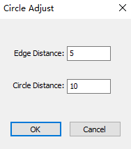
Adjust Circle
It is used to change the distribution of certain circles, so as to solve the problem that the circles cannot be filled in certain regions or its filling effect is not good.
Operation Steps:
In the menu bar, click Nest → Advertise Words Fill → Circle Adjust.
Set parameters Edge Distance and Circle Distance.
 .
.Click OK, the cursor becomes to
 .
.Select the target region.
The system automatically deletes circles in the target region and according to the set Edge Distance and Circle Distance, use rectangle filling to fill the circle hole in this area.
Right click or press ESC to exit.
Erase Circle
It is used to delete redundant circles in the objects.
Operation Steps:
- In the menu bar, click Nest → Advertise Words Fill → Circle Erase. The cursor becomes .
- Select the target region. The system automatically deletes circles in the target region.
- Right click or press ESC to exit.