Scan Cutting
It is used to re-plan a tool path to find the most efficient path to execute machining by controlling laser on/off, so as to avoid unnecessary tool lifting and feeding and improve machining efficiency.
According to different cutting graphics, the scan cutting methods are divided into:
- Line Scan: Identify objects as lines.
- Arc Scan: Identify objects as arcs.
- Runway Scan: Identify objects as a graphic similar to a playground runway.
- Ring Scan: Identify objects as nested ring graphic inner and outer.
- Sector Scan: Identify objects as sector graphic.
- LED Scan: Identify objects as graphic filled with small circles.
Line Scan
Operating Steps:
Select multiple objects.
Select the following method to open the Line Scan dialog box:
In the common toolbar, click
 Scan.
Scan.In the common toolbar, click
Scan drop down box → Line Scan.In the menu bar, click Tool Path → Scan → Line Scan.
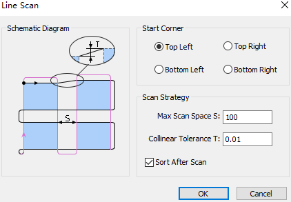
Select the tool start position and set the following parameters:
Max Scan Space: The distance between the two collinear graphics is greater than the maximum scan space set, and they are divided into two groups for scanning.
Collinear Tolerance: If the distance between two parallel lines in objects is less than the set value, the two lines are regarded as collinear.
Check Sort after Scan as needed.
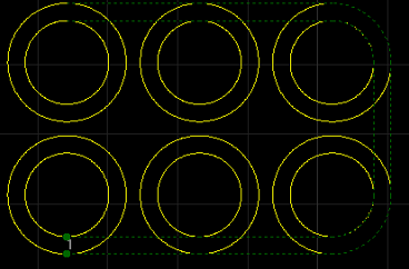
The effect diagram of line scan is as follows:
Arc Scan
Operation Steps:
Select multiple objects.
Select the following method to open the Arc Scan dialog box:
In the common toolbar, click
Scan drop down box → Arc Scan.In the menu bar, click Tool Path → Scan → Arc Scan.
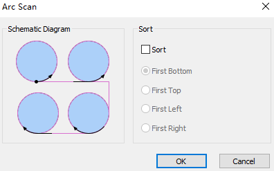
Optional: If need to scan the selected circle according to the sort strategy, check Sort and select the sort strategy.
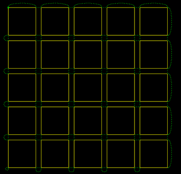
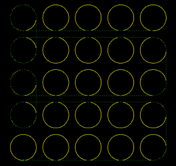
The effect diagram of arc scan is as follows:
LED Scan
Operation Steps:
Select multiple objects.
Select any of the following methods to open the Scan LED on Text dialog box:
In the common toolbar, click
Scan drop down box → LED Scan.In the menu bar, click Tool Path → Scan → LED Scan.
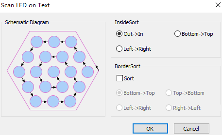
Set inside and border sort:
Inside Sort: To sort all circles in the inner of the target objects, and form a scanning group.
Border Sort: To sort objects based on the frames of the target objects.
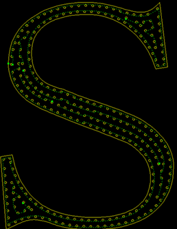
The effect diagram of LED scan is as follows:
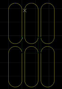
Runway Scan
Operation Steps:
Select multiple objects.
Select any of the following options to open the Runway Scan dialog:
In the common toolbar, click
Scan drop down box → Runway Scan.In the menu bar, click Tool Path → Scan → Runway Scan.
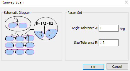
Set the following parameters:
Angle Tolerance: If the angle difference is less than the set tolerance, the target objects are parallel. Range: 0°~5°.
Size Tolerance: If the height difference between two runways is less than the set tolerance, the sizes of target objects are the same. Range: 0mm~1mm.
The effect diagram of runway scan is as follows:
Sector Scan
Operation Steps:
Select multiple objects.
Select any of the following methods to open the Sector Scan dialog box:
In the common toolbar, click
Scan drop down box → Sector Scan.In the menu bar, click Tool Path → Scan → Sector Scan.
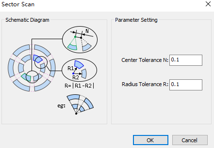
Set the following parameters:
Center Tolerance: If the distance between circle centers of two circular rings is less than the set tolerance, the target objects are in a scanning group.
Radius Tolerance: If the radius difference between two circular rings is less than the set tolerance, the target objects are in a scanning group.
The effect diagram of sector scan is as follows:
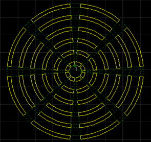
Ring Scan
Operation Steps:
Select multiple objects.
Select any of the following methods to open the Ring Scan dialog:
In the common toolbar, click
Scan drop down box → Ring Scan.In the menu bar, click Tool Path → Scan → Ring Scan.
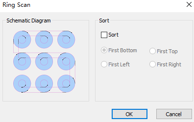
Optional: If need to scan the selected ring according to the sort strategy, check Sort, and select the sort strategy.
Click OK, the system scans automatically.
The effect diagram of ring scan is as follows: