Laser
This section introduces wiring methods for different brands of lasers.
Before connecting the laser, do the following preparation:
Connect to applicable pulse modulation signals based on the laser.
The pulse modulation signals provided by the NcStudio V15 laser cutting control system and the corresponding EX33A ports are shown below:
- +24V single-ended signal: MOD(24V) & COM
- +5V single-ended signal: MOD(5V) & COM
- ±5V differential signal: MOD(+) & MOD(-)
If the laser supports RS232 communication, you can use a DB9 cable to connect the laser RS232 port to the EX33A RS232 to achieve communication between the laser and the software.
RS232 is a serial communication standard developed by the U.S. Electronic Industry Association along with Bell System, and modem and computer manufacturers.
It is applicable to communication with a data transmission rate of 0 b/s–20000 b/s. Commonly used for communication within 20m.
The wiring diagrams for the following lasers are provided below for your reference:
Note: All MOD pins of EX33A extension terminal boards shown in the following diagrams are MOD(24V).
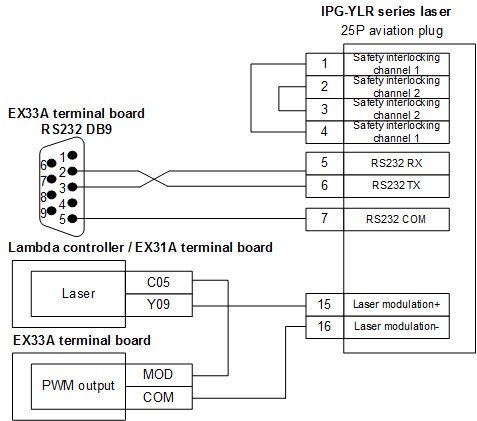
IPG-YLR Series Laser
The wiring diagram is shown below:
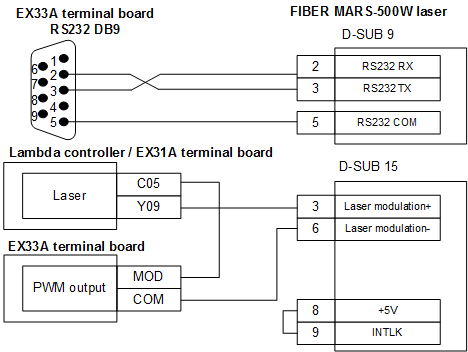
Feibo MARS-500W Laser
The wiring diagram is shown below:
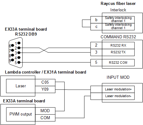
Raycus Fiber Laser
The wiring diagram is shown below:
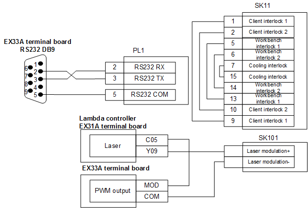
JK / GSI-500W-FL Laser
The wiring diagram is shown below:
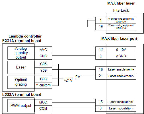
MAX Fiber Laser
The wiring diagram is shown below:
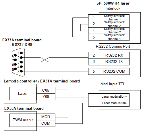
SPI-500W-R4 Laser
The wiring diagram is shown below:
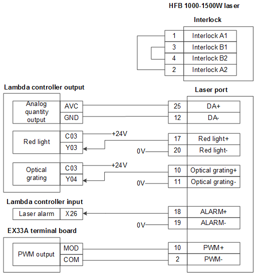
HFB 1000-1500W Laser
The wiring diagram is shown below:
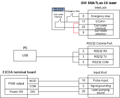
GW SMATLas 3S Laser
The wiring diagram is shown below: