Basic Editing
It is used to edit drawn and imported objects, so as to modify the toolpath according to the requirement.
It includes the following:
- Translate objects
- Rotate an object
- Mirror an object
- Align objects
- Scale objects
- Merge objects
- Share an edge
- Group objects
- Ungroup objects
- Explode objects
- Break objects
- Execute array
After editing objects, you can click File → Export File to import the target objects as a DXF / DWG file in the menu bar for later use.
Translate Objects
It is used to move objects a certain distance. As a result, the coordinate of objects will be changed without changing the size of objects.
To translate objects, select the target objects, and do the following:
Press the left mouse button and drag the objects.
On the keyboard, press ↑ / ↓ / ← / →.
Call Translate command:
Click
 Transf → Translate in the common toolbar, or click Edit → Translate in the menu bar.
Left click on the drawing window.
Move the cursor to the target position and click again.
Rotate an Object
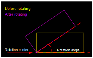
It is used to move or turn an object around a certain fixed point, so as to change the position and direction of the object.
To rotate an object, select the target object, and do one of the following:
Left click to define a point.
The point is the rotation center by default.
In the common toolbar, enter the rotation angle in Angle input box and press Enter.
If the object is a rectangle or text, the lower left point of the object is the rotation center.
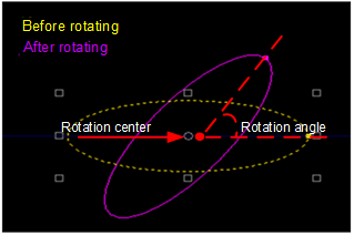
If the object is a/an star, polygon or ellipse, the center point of the object is the rotation center.
Call Rotate command:
In the common toolbar, click
Transf→ Rotate, or click Edit → Rotate.Left click to select the rotation center.
Move the cursor to adjust the rotation angle.
Left click to confirm.
Mirror an Object
It includes the following:
Vertical mirror: mirror along X-axis with the center of the object as the center of rotation.
Horizontal mirror: mirror along Y-axis with the center of the object as the center of rotation.
To mirror an object, select an object, and do one of the following:
In the common toolbar, click
Transf → Vertical Mirror / Horizontal Mirror.In the menu bar, click Edit → Mirror → Vertical Mirror / Horizontal Mirror.
Align Objects
It is used to arrange the objects in a straight line.
To align objects, select several objects and do one of the following:
To align objects by the center point, in the drawing toolbar, click
 .
.In the menu bar, click Edit → Align, and select one of the following:
- Align Left
- Align Right
- Align Top
- Align Bottom
- Align Center Point
- Align Horizontally
- Align Vertically
- Distribute Horizontally
- Distribute Vertically
The system automatically aligns objects.
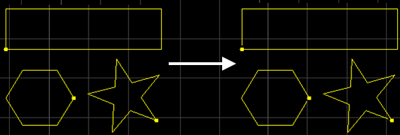
Scale Objects
It is used to make objects appear larger/smaller in the equal proportion.
To scale objects, select the target objects, and do the following:
In the common toolbar, enter the scaling factor in Scale input box and press Enter.
In the menu bar, call Scale command:
Click Edit → Scale.
Left click to select the center point for scaling.
Move the cursor to adjust the scaling factor.
Left click to confirm.
Merge Objects
It is used to combine unclosed objects within the set tolerance, so as to help to avoid unnecessary tool lifting and improve machining efficiency.
Tolerance is the allowable distance between objects that need to be combined.
The target objects cannot be the following:
- Closed object
- Dot
- Text
- Group
Before merging objects, it is suggested to enable catch options.
To merge objects, select the target objects, and do the following:
To open Join dialog box, do one of the following:
In the common toolbar, click
 Merge.
In the menu bar, click Edit → Merge.
Right click on the drawing window and select Merge.
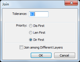
Set parameter Tolerance.
Range: 0.01mm~10mm
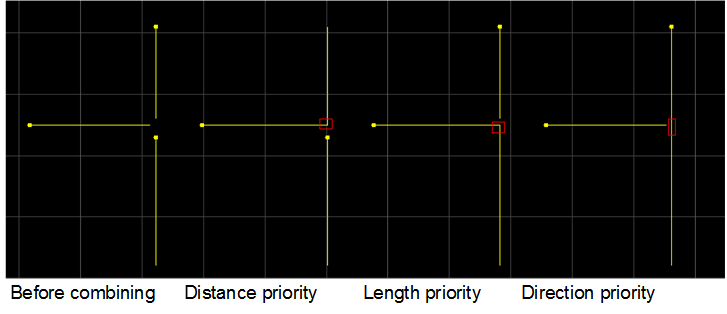
Select a priority strategy to decide the standard for combining.
If there exist more than two end points that can be combined, the system combines objects that are nearest / longest / in the same direction.
Optional: Check Merge among different layers. The system merges objects of different layers into the layer with a higher layer order.
The result is as follows:
Share an Edge
It is used to make the overlapped edges become a shared edge, so as to avoid cutting the same edge during machining, and optimize the toolpath.
The error for sharing an edge is 0.1mm.
Before sharing an edge, make sure the following:
The shared objects are closed objects and share the same point.
The shared edge is a line or an arc.
To share an edge, select at least two objects, do the following:
To open Common Edge dialog box, do one of the following:
In the menu bar, click Planning → Common Edge.
Right click on the drawing window, and click Common Edge.
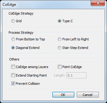
Select a strategy for sharing an edge:
- Grind: cut internal objects first.
- C Type: cut objects in the shape of character C.
Optional: If the strategy is C Type, select a machining order:
From Bottom to Top: cut objects from bottom to top.
From Left to Right: cut objects from left to right.
Diagonal Extend: cut objects in the lower-left region first and cut its adjacent objects circle. The toolpath is like an ever-widening arc. The marching direction is from the lower-left region to the upper-right region.
Stair-step Extend: it is applicable to rectangular objects. Its toolpath is like stair steps. The extending direction is from the lower-left region to the upper-right region.
Optional: Check the following items in Others area:
Share Edge among Layers: to make objects in the different layers share the edge.
Share Point: to make objects that share the same point as a group.
Extend Starting Point: to extend the toolpath in the opposite machining direction through the start point and turn on the laser in advance, helping completely cut the start point and avoid over-burning.
It is applicable to rectangular objects.
Prevent Collision: to avoid colliding with the cutting head after cutting parts in the first region of shared objects.
It is only applicable to strategy C Type. With it checked, the shared edge will be cut in the second region. Otherwise, the shared edge will be cut in the first region.
After sharing an edge, the objects turn into a group.
Group Objects
It is used to bind several objects, so as to edit them at the same time.
To group objects, select several objects, and select one of the following:
In the common toolbar, click
 Group.
In the drawing window, right click and select Group.
In the menu bar, click Edit → Group/Ungroup → Group.
The result is as follows:

Ungroup Objects
It is used to separate the grouped objects, so as to edit each part of the objects independently.
To ungroup objects, select the target group, and do one of the following:
In the common toolbar, click
 Ungroup.
Right click on the drawing window and select Ungroup.
In the menu bar, click Edit → Group/Ungroup → Ungroup.
Explode Objects
It is used to delete extra lines, so as to trim the toolpath. It usually applies to polylines.
It is suggested to use it together with merging function, to correct mistakes by drawing and make sure machining quality:
If the object is a group, exploding objects is equal to ungrouping objects.
If the object is text, exploding objects is equal to turning the text into polylines.
To explode objects, select the target objects, and do one of the following:
In the common toolbar, click
 Explode.
In the menu bar, click Edit → Explode.
The result is as follows:
Break Objects
It is used to cut objects into several polylines.
It is usually used in the following situations:
Connect the cutting part to its surrounding material. It equals to micro joint.
Cut extra objects during drawing objects.
To break objects, do one of the following:
To break all the selected objects at the same time, automatically break objects.
To break one object each time by freely selecting breaking position, manually break an object.
Automatically Break Objects
To automatically break objects, select the target objects, and do the following:
In the menu bar, click Edit → Break. Break dialog box pops up:
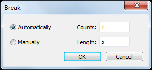
Select Automatically and enter the number and distance of breaking lines.
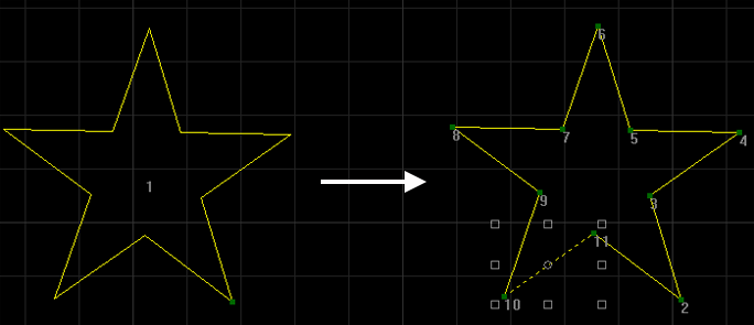
The result is as follows:
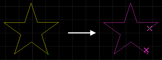
Manually Break an Object
To manually break an object, do the following:
In the menu bar, click Edit → Break. Break dialog box pops up:
Select Manually and enter the distance of breaking lines.
Click OK. The cursor turns to
 .
.Left click to select the positions for breaking.
Right click to finish breaking.
The result is as follows:
Execute Array
It is used to copy the machining objects and arrange them in order, so as to improve machining efficiency.
Array includes the following:
Execute Rectangular Array
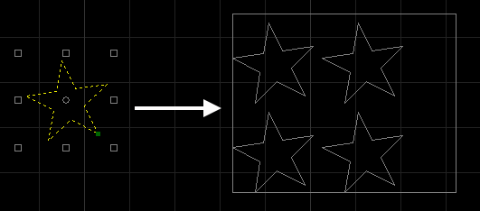
It is used to copy the machining objects and arrange them in a rectangular array.
To execute rectangular array, select the target objects, and do the following:
To open Rectangular Array dialog box, do one of the following:
In the common toolbar, click
 Array.
In the common toolbar, click the drop-down box of
Array, and select Rectangular Array.In the menu bar, click Drawing → Array → Rectangular Array.
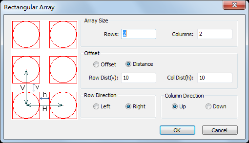
Set the number of rows and columns for array.
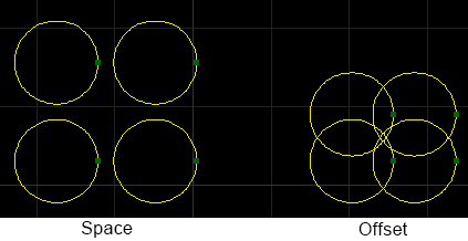
In Offset area, select one of the following ways:
Offset: based on the center of the object.
Space: based on the frame of the objects.
Select the direction for rows and columns.
The result is as follows:
Execute Circular Array
By taking a certain point as the center, it is used to copy the objects and arrange them in a circle array.
To execute circular array, select the target object, and do the following:
To open Circular Array dialog box, select one of the following:
In the common toolbar, click the drop-down box of
Array, and select Circular Array.In the menu bar, click Drawing → Array → Circular Array.
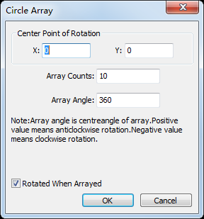
Set coordinates of the center point for rotation.
Set parameters Array Counts and Array Angle.
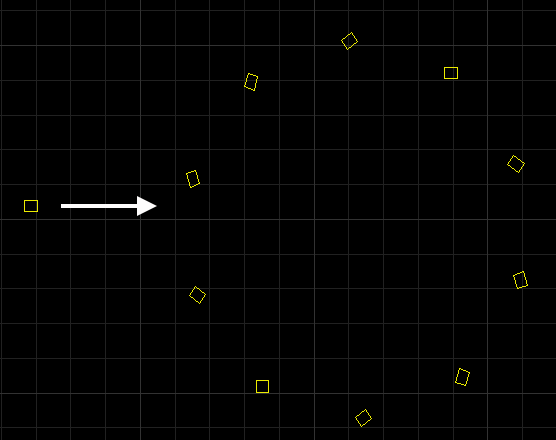
The result is as follows:
Execute Manual Array
It is used to manually draw a range shaped in a rectangle for array. Objects will be copied in the rectangle.
To execute manual array, select the target object, and do the following:
To open Manual Array dialog box, select one of the following:
In the common toolbar, click the drop-down box of
Array, and select Manual Array.In the menu bar, click Drawing → Array → Manual Array.
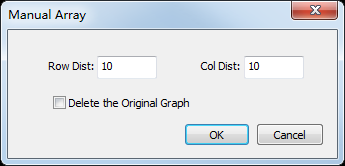
To set the space between rows and columns, set parameters Row Dist and Col Dist.
Optional: To delete the original object after array, check Delete the Original Graph.
Click OK. The cursor turns into
 .
.To select the start position, right click.
Optional: To enter into manual array, right click on the drawing window.
Note: Without selecting the start position, right clicking on the drawing window will exit manual array.
To select the end position, drag the mouse and left click.
The result is as follows: