Set Kerf Compensation
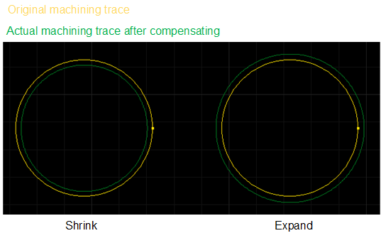
There exists deviation between the sizes of actual cutting parts and theoretical ones, which is caused by the kerf during cutting. The deviation leads to a smaller size in the outer contour and a larger size in the inner contour. This operation is used to compensate the deviation.
The type of kerf compensation includes the following:
All shrink: shrink the cutting area for all selected parts.
All expand: expand the cutting area for all selected parts.
Unfill: shrink; fill: expand: shrink the cutting area for parts with unfill attribute, and expand the cutting area for parts with fill attribute.
Before setting kerf compensation, make sure the following:
The text has been turned into polylines. See Turn Text into Polylines for details.
At least a closed object exists.
To compensate the kerf, select the closed objects, and do the following:
To open Kerf Compensation dialog box, do one of the following:
In the common toolbar, click
 Comp.
Comp.In the menu bar, click Technics → Kerf Compensation.
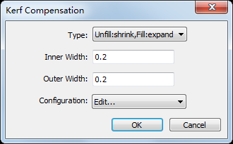
Select a compensation type.
Set the inner width and outer width.
Optional: To save the commonly used inner width and outer width for later use, do the following:
In the drop-down box of Configuration, select Edit. Configuration dialog box pops up:
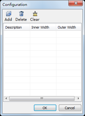
Click Add, set a name in Description column, set the inner width in Inner Width column, and set the outer width in Outer Width column.
For later use, in the drop-down box of Configuration, select the set name. The system automatically fills in the inner width and outer width.
The result is as follows: