Set Scan Cutting
It is used to replan a toolpath to find the most efficient path to execute machining by controlling laser on/off, so as to avoid unnecessary tool lifting and feeding and improve machining efficiency.
It differs in the object type:
- Set scan cutting for lines.
- Set scan cutting for circles.
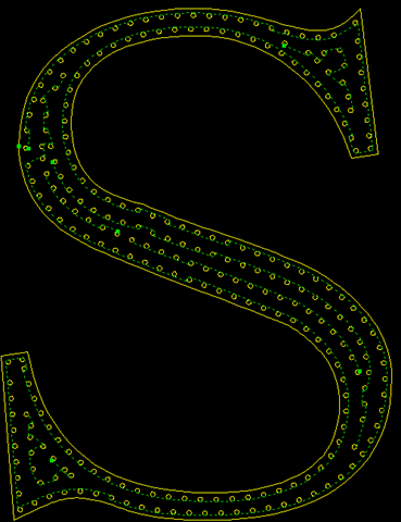
- Set scan cutting for LED advertisement text.
Set Scan Cutting for Lines
To set scan cutting for lines, select the target objects, and do the following:
To open Line Scan pops up, do one of the following:
In the common tool bar, click
 Scan.
Scan.In the common tool bar, click the drop-down box of
 Scan, and select Line Scan.
In the menu bar, click Planning → Scan → Line Scan.
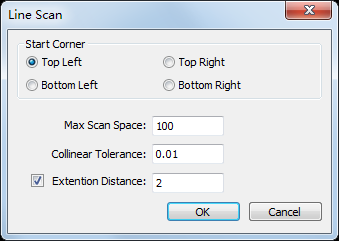
Select the start position for cutting, and set parameter Colinear Tolerance and Max Scan Space.
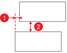
①: Collinear Tolerance; ②: Max Scan Space.
Optional: Check Extension Distance and set a value.
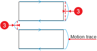
③: Extension Distance
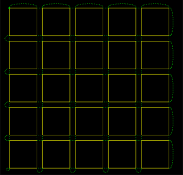
The result is as follows:
Set Scan Cutting for Circles
To set scan cutting for circles, select the target objects, and do the following
To open Arc Scan dialog box, do one of the following:
In the common tool bar, click the drop-down box of
 Scan, and select Arc Scan.
In the menu bar, click Planning → Scan → Arc Scan.
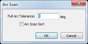
Set parameter Full Arc Tolerance.
Optional: To sort the selected circles by the default array sorting strategy, check Arc Scan Sort.
The result is as follows:

Set Scan Cutting for LED Advertisement Text
To set scan cutting for LED advertisement text, select the target objects, and do the following:
To open LED Scan dialog box, do one of the following:
In the common tool bar, click the drop-down box of
 Scan → LED Scan.
In the menu bar, click Planning → Scan → LED Scan.
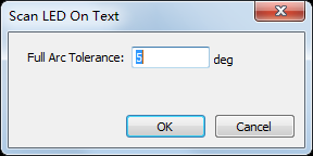
Set parameter Full Arc Tolerance.
The result is as follows:
