Main Interface
Through this part, you can quickly know the layout of the main interface for NcStudio V15 Laser Cutting (Tube) CNC System.
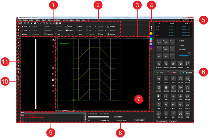
- Menu bar
- Common tool bar
- Drawing window
- Layer tool bar
- Window display button
- Machine control area
- Status area
- Statistics area
- Alarm/system info area
- Drawing tool bar
- 3D view area
Common Tool Bar
It is used to show the following frequently used instructions:
 : New
: NewUsed to create a new toolpath file by selecting a kind of tube type and setting parameters for the section.
 : Import
Used to import an
IGS/IGESfile. : Open
Used to open a
NCEXfile. : Save
Used to save a toolpath file.
A new file is saved as a
NCEXfile. : Undo
Used to go back to a previous state.
 : Redo
Used to recover canceled operations.
 : Show order
Used to show or hide the machining order.
 : Show direction
Used to show or hide the machining direction.
 : Highlight unclosed objects
Used to mark all unclosed objects with red color.
 : Clear trace
Used to clear the machining trace.
 : Catch
Used to enable/disable catching function.
 : Catch options
Used to open Catch Options dialog box and set options for catching.
 : Select
Used to select unclosed objects, tiny objects, inner objects, outer objects, similar objects. See Select Objects for details.
 : Transform
Used to translate objects, rotate objects, mirror objects vertically or horizontally. See Translate Objects and Rotate an Object for details.
 : Clear
Used to clear some set technics. See Do Clearing for details.
 : Merge
Used to open Combine dialog box and combine objects. See Merge Objects for details.
 : Explode
Used to trim the toolpath. See Explode Objects for details.
 : Smooth curve
Used to make polylines flat and even. See Smooth Curves for details.
 : Preprocess
Used to open Instant Pre-process dialog box when several target objects are selected and preprocess objects with one click. See Preprocess with One Click for details.
 : Lead line
Used to open Set dialog box and set a lead line. See Set a Lead Line for details.
 : Start point
- With a lead line: used to set the start point of the lead line.
- With no lead line: used to set the current point as the start point.
 : Micro joint
Used to open Micro Joint dialog box and set related parameters. See Execute Micro Joint for details.
 : Cool point
Used to open Cooling Point dialog box and add cooling points. See Add Cooling Points for details.
 : Unfill / fill
Used to set fill or unfill. See Set Fill or Unfill for details.
 : Mach direction
Used to open Set Machining Direction dialog box and set machining direction. See Change the Machining Direction for details.
 : Bridge
Used to open Bridge dialog box and bridge objects. See Bridge Objects for details.
 : Compensate
Used to open Kerf Compensation dialog box and compensate the kerf. See Compensate the Kerf for details.
 : Chamfer
Used to open Chamfer dialog box and add chamfers. See Add Chamfer.
 : Sort machining order
Used to set the machining order. See Change the Machining Order for details.
 : Scan cut
Used to replan the toolpath to find the most efficient path for machining, so as to avoid unnecessary tool lifting and feeding and improve machining efficiency. See Set Scan Cutting for details.
 : Instant setting
Used to set fill/unfill, lead line, machining direction, machining order and kerf compensation with one click. See Execute Instant Setting for details.
 : Tube array
Use to nest objects. See Execute Tube Array for details.
 : Rectangular array
Use to execute rectangular array. See Execute Rectangular Array for details.
 : Follow-up
Used to open Follow-up Control dialog box. See Calibrate Capacitance for details.
 : Control focus
Used to open Focus Control dialog box. See Control the Focus for details.
 : Common Param
Used to open Common Param dialog box, set frequently used machine parameters, user habit, gas parameters, burst parameters, and switch unit.
Drawing Window
It is used to draw and preview objects.
In tube cutting configuration, the development effect of a rectangular tube shows in drawing window for ease of drawing:
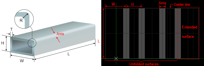
Length of an arris: depending on the corner radius and thickness of the rectangular tube.
Extended face: corresponding to the first face of the actual tube.
Center line: including face center line and arris center line. It exists on each face. When you drag the object, the center of the object automatically gets close to the center line.
Layer Tool Bar
It is used to do operations related to layer.
It includes the following:


See Layer Interface for details.
Window Display Button
It is used to show/hide the machine control area.
See Machine Control Area for details.
Machine Control Area
It includes the following:
Axis Coordinate Display Area
It is shown as follows:
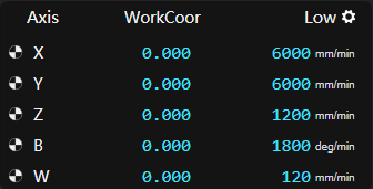
After returning to the machine origin, sign  appears in front of each axis.
In this area, you can do the following:
To switch among workpiece coordinates, machine coordinates and feedback coordinates, do one of the following:
Double click Work/Machine/Feedback.
Move the cursor to character Work/Machine/Feedback, and click
 .
.
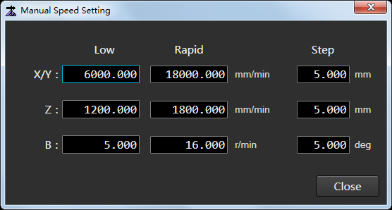
To separately set low speed, rapid speed and step size for X/Y-axis, Z-axis and B-axis, click
 :
:
Manual Control Area
It is used to move the machine tool.
It is shown as follows:

Axis direction buttons
Used to move each axis towards positive or negative direction.
Feed mode buttons
To switch to Jog mode, click Jog.
In this mode, click an axis direction button or several axis direction buttons. The clicked axis/axes move(s) at jog speed until you release the button(s).
To switch to Rapid Jog, click Jog → Rapid.
In this mode, click an axis direction button or several axis direction buttons. The clicked axis/axes move(s) at rapid jog speed until you release the button(s).
To switch to Step mode, click Step.
Click an axis direction button. The clicked axis moves the customized step size.
The default customized step size is 5mm. And you can customize the step size in axis coordinate display area.
Note: Please do not click an axis direction button too frequently because the system needs a certain time to execute the command.
Feed override area
Used to adjust the current feed override before machining to during machining, so as to adjust G00 speed or machining speed.
The relation between G00 speed or machining speed and feed override is as follows:
Current rapid traverse speed/machining speed = Current feed override * Set value of G00/machining speedTo adjust feed override, do one of the following:
- Drag the slider.
- Click the target position on the slider.
- Click the slider and press PgUp / PgDn or ↑ / ↓ on the keyboard.
Common Operation Buttons
It is used to execute the following common operations:
 : Set origin
Used to set the workpiece origin.
 : To origin
Used to move the feeding axis, horizontal moving axis, lifting axis, rotary axis or focus axis to workpiece origin.
 : Go home
Used to return all axes to the machine origin.
 : Z home
Used to return Z-axis to the machine origin.
 : Calibrate
Used to set a follow-up height.
Machining Control Area
It includes the following:
 : Start
Used to start machining from the beginning.
 : Stop
Used to stop machining.
 : Resume
Used to resume machining from the exact interrupted position when the power interruption or e-stop occurs and the workpiece origin is secured.
 : Simu
Used to execute simulation to check the toolpath in real-time.
 : Dry run
Used to run the machine tool without turning on related ports of laser and machining. There is no actual machining.
 : Return to center
Used to move the rotary axis to the workpiece origin or the horizontal moving axis to the center line of the tube.
See Execute Returning to the Center for details.
 : Tube centering
Used to adjust the tube horizontally and find the center line for a certain face of the tube.
See Level and Center the Tube for details.
 : Centering mode
Used to switch between the following centering modes:
- Standard: levelling + centering
- Simple: centering
 : F chuck released
Used to control the unclamping of the front chuck.
After setting the chuck control type in the system parameters, the chuck can be controlled by IO / torque / position.
 : F chuck clamped
Used to control the clamping of the front chuck.
After setting the chuck control type in the system parameters, the chuck can be controlled by IO / torque / position.
 : B chuck released
Used to control the unclamping of the back chuck.
 : B chuck clamped
Used to control the clamping of the back chuck.
 : Laser
Used to turn on/off the laser valve.
It is automatically turned on when machining starts.
 : Shutter
Used to manually turn on laser shutter.
To eject laser light, first, turn on the laser shutter; then, open the laser valve.
 : Red light
Used to manually turn on the red light.
It is used as a kind of guide light to point out the laser position on the tube.
 : Burst
Used to turn on the laser valve for a certain time.
It keeps on for the set burst time until it is turned off automatically.
 : Dispose tailing
Used to dispose the tailing.
During disposing the tailing, please ensure the following:
The system is in idle status.
The feeding axis, horizontal moving axis, lifting axis, clamping axis for blanking plate, forward and backward moving axis for blanking plate have been returned to the machine origin.
 : Follow-up
Used to turn on follow-up valve, to keep the distance between the nozzle and the workpiece surface a fixed value.
It is turned on automatically when machining starts.
 : Air
: AirWhen machining starts, the button is highlighted. The system automatically turns on the blowing valve and blows air.
 : Oxygen
When machining starts, the button is highlighted. The system automatically turns on the blowing valve and blows oxygen.
 : Nitrogen
When machining starts, the button is highlighted. The system automatically turns on the blowing valve and blows nitrogen.
 : Auto loaded
Used to automatically load material after setting parameter Enable Automatic Loading Device to Yes.
 : Fan
: FanUsed to turn on the fan.
 : Deslag
Used to automatically deslagging after setting parameter Enable Back Blow or Enable Side Blow to Yes.
 : Lubricate
Used to turn on lube.
 : Edge find
With the button clicked, the cutting head starts to find the tube edge.
 : Reserved
Status Area
It is shown as follows:

You can check the following in the area:
Related information of current drawing objects: drawing steps and meaning, step result, tuning distance, etc.
Tips during machining.
Statistics Area
It is shown as follows:
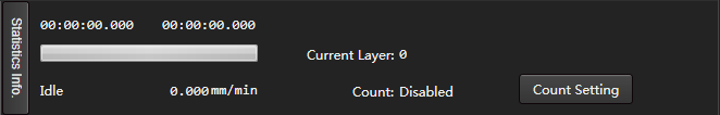
You can do the following in the area:
To open Statistic Information dialog box, click Statistics Info.
See Check Statistics for details.
To open Count Setting dialog box, click Count Setting.
See Count Machining for details.
Alarm/System Info Area
It is shown as follows:
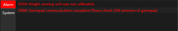
You can do the following in the area:
To open Log dialog box, double click Alarm / System.
See Check System Logs for details.
To troubleshoot the alarm or check the log details, double click the related alarm items or system information items.
Drawing Tool bar
It is used to do the following:
3D View Area
It is shown as follows:
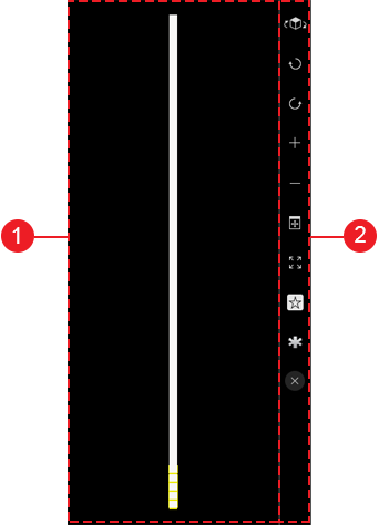
View Area
It is used to check the tube from different perspectives and preview cutting effect.
In this area, you can do the following:
Press the left button:
- To rotate the tube, drag the mouse left and right.
- To move the tube, drag the mouse up and down.
To zoom in/out the tube, scroll the mouse wheel.
View Tool Bar
It includes the following:
 : Switch view
Used to observe a tube from different perspectives.
 : Rotate CW
Used to rotate the view in a clockwise direction.
 : Rotate CCW
Used to rotate the tube view in a counterclockwise direction.
 : Zoom in
Used to make the view appear larger.
 : Zoom out
Used to make the view appear smaller.
 : Best view
Used to adjust 3D view area to the best size, so as to check the toolpath effect.
 : Maximize
Used to maximize 3D view area and hide drawing window.
 : Hollow out
Used to show hollow-out-effect of objects, so as to check the cutting effect.
 : Solid
Opposite to
instruction. : Instant Hollowing
Used to show hollow-out-effect of objects which have been executed machining or dry run, while executing
instruction for other objects. : Tube cutting setting
Used to open Tube Cutting Setting dialog box. See Set the Tube Type and Size for details.
 : Close
Used to close 3D view area.