Machining Technic
Overview
The machining technic can be set on the Software Main Interface and 2D Edit pages. This chapter will introduce all the machining technic functions. If the function entries supported by the two pages are the same, it will not be emphasized in which page to set.
Lead Line
It is used to avoid machining errors or damage to the workpiece caused by laser staying above the start position for a long time, so as to improve machining accuracy.
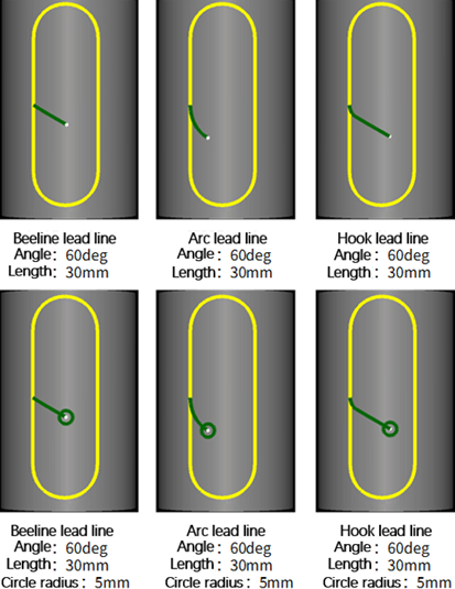
The types of lead line are divided into:
- Lead-in: consisting of line lead line, arc lead line and hook lead line.
- Lead-out: consisting of line lead line and arc lead line.
Operation Steps:
Select one or more graphics.
Select any of the following methods to open the Lead Line dialog box:
In the Tech area of the Common menu bar, click
 → Set.
Right click, and click Lead Line → Set in the shortcut menu.
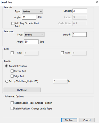
In the Lead-in and Lead-out areas, set the lead-in and lead out types and related parameters. The parameters are described as follows:
Angle: For a line-type lead line, it refers to the angle between the lead line and the tangent line of the intersection; for an arc-type lead line, it refers to the central angle.
Length: For a line-type/arc-type lead line, it refers to the length of the line/arc; for a hook-type lead line, it refers to the sum of the radius of the arc and the length of the line.
Radius: For a hook-type lead line, it refers to the radius of the arc.
Add Tiny Circle in Start Point: Add a tiny circle at the start point of the lead-in line, so as to solve the problem that the accumulation of slag influences cutting effect during piercing a thick tube.
Circle Radius: The radius of the hole at the start point of the lead line.
(Optional: ) If the target object is a closed object, in Seal area, select one of the following.
Gap: The lead line is unclosed and the cutting head will not cut through at the sealing position.
Over: The lead line is closed and the cutting head will cut at the sealing position.
In the menu bar, click
→ Seal → Notch / Overcut to edit or delete gaps and overcut separately.Set the position of the lead line:
If you check Auto Set Position, do one of the following:
Corner First: Add lead line at the corner first.
Edge First: Add lead line at the longest edge first.
If Set by Total Length (0 ~100) is selected, set the percentage of the position from the start point of machining to the lead line in the total side length of the graphic.
Available only for closed graphics.
If you click By Mouse, the cursor will become to
 . Click the graphic edge to manually specify the position of the lead line. After setting, right click or press Esc to exit the tool.
In the Advanced Area, select as needed: Retain Leads Type, Change Position / Retain Position, Change Leads Type.
(Optional: ) To manually modify the lead line position, perform the following steps:
Select the following methods to use the manual set start point function.
In the menu bar, click
→ Set Start Point.Right click and click Lead Line → Start Point.
Click the left mouse button on the graphic edge to modify the position of the lead line without modifying the angle and length.
Right click or press ESC to exit the start point function.
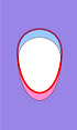
Effect picture:
Kerf Compensation
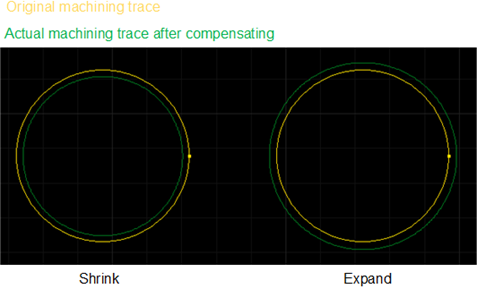
Laser cutting has kerf (the part of loss during cutting), which makes the size of the part actually cut deviate from the theoretical size of the part. This operation can compensate the geometric dimension of the deviation.
The type of kerf compensation includes the following:
All Shrink: Shrink the cutting area for all selected parts.
All Expand: Expand the cutting area for all selected parts.
Unfill: Shrink, Fill: Expand: Shrink the cutting area for parts with unfill attribute, and expand the cutting area for parts with fill attribute.
Prerequisite:
Before compensating the kerf, ensure the following:
The text has been turned into polylines.
It is not dot, auxiliary line, over tangent, over arris, scan, self intersection and co-edge graphic.
Operation Steps:
Select one or more graphics.
In the Tech area of the Common menu bar, click
 to open the Kerf Compensation dialog box:
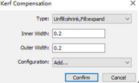
Click the Type drop-down box to select a compensation type.
Set the inner width and outer width.
(Optional: ) To save the commonly used inner width and outer width for later use, do the following:
In the drop-down box of Configuration, select Add. Configuration dialog box pops up
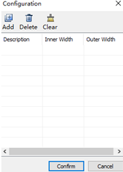
Click Add, set a name in Description column, set the inner width in Inner Width column, and set outer width in Outer Width column.
For later use, in the drop-down box of Configuration, select the name set in the Description column. The system automatically fills in the inner width and outer width.
Effect picture:
Corner Chop
It is mainly used for graphics spanning 2~3 faces. In actual cutting, this kind of tool path is difficult to fall off after cutting, and it is automatically marked before cutting to facilitate the waste falling off.
Prerequisite:
Before corner chop an object, ensure the object meets the following requires:
Unfill.
Non text.
Over arris closed graphic spanning 2~3 sides.
Micro joint and chop are not added.
No other graphics are included.
Operation Steps:
Select one or more graphics.
The path to open the Corner Chop dialog box varies according to the interface:
- In the Software Main Interface, in the Tech area of the Common menu bar, click
 → Corner Chop.
 - In the 2D Edit page, in the Tech area of the Common menu bar, click
 .
.

- In the Software Main Interface, in the Tech area of the Common menu bar, click
Set parameters. The parameters are described as follows:
Chop Line Offset: The distance between the start point of the chopping line and the hole.
Chop Line Distance: The distance between the chopping line and the arris.
Chop Line Number: Select 1 or 2.
Click Confirm.
Effect picture:

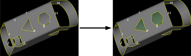
Grid Chop
Divide the selected graphic into multiple blocks, that is, chop the machining waste to facilitate the waste falling off.
Prerequisite:
Before chop an object, ensure the object meets the following requires:
Non text.
Non over arris graphic.
Unfill.
Close graphic.
Large graphics, and the minimum distance between the chop line and the entity frame is 0.3mm, and the minimum length of the chop line is 1mm.
No micro joint was added.
No other graphics are included.
Operation Steps:
Select one or more drawings.
The path to open the Chop dialog box varies according to the interface:
- In the Software Main Interface, in the Tech area of the Common menu bar, click → Grid Chop.
- In the 2D Edit page, in the Tech area of the Common menu bar, click
 .
.
- In the Software Main Interface, in the Tech area of the Common menu bar, click
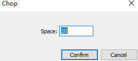
Set the chop space.
Effect picture:
Micro Joint
Micro joints can be used to connect parts with surrounding materials, so that materials do not fall and sorting is not required. At present, the section steel does not support micro joint of the cutoff line.
The following two micro joint settings are supported:
Set automatic micro joint: The system automatically adds micro joint to the selected objects according to the set values.
Set manual micro joint: Select the micro joint position by yourself.
Automatic Joint
Operation Steps:
Select the object.
In the Tech area of the Common menu bar, click
 to open the Micro Joint dialog box:
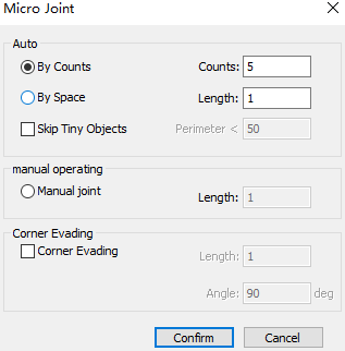
In the Auto area, select by counts or space to micro joint.
The system automatically executes micro joints on the selected objects according to the set values.
(Optional: ) Check Skip Tiny Objects and set the perimeter.
Small graphics within the perimeter will not be micro joints.
Check Corner Evading and set the following parameters:
Length: In the range of evade length, the corner cannot be added micro joint. Range: 0.001 mm ~10 mm.
Angle: Range: 90 ° ~180 °.
If Corner Evading is not checked, all points support micro joint.
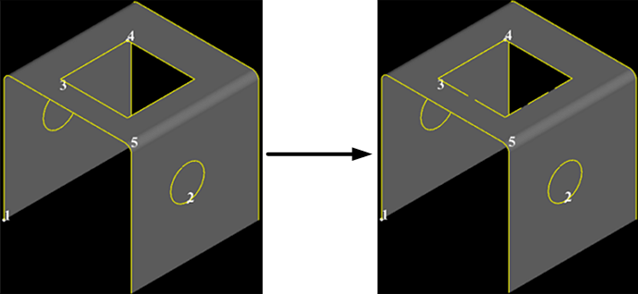
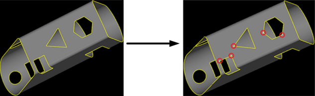
When By Counts micro joint is selected and the set quantity is 5, the effect before and after the automatic micro joint is as follows:

Manual Joint
Operation Steps:
You do not need to select an object. In the Tech area of the Common menu bar, click
to open the Micro Joint dialog box: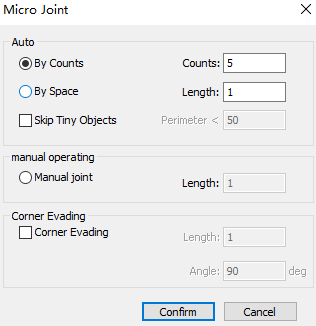
In Manual Operating area, select Manual Joint, and set parameter Length.
Check Corner Evading and set the following parameters:
Length: In the range of evade length, the corner cannot be added micro joint. Range: 0.001 mm ~10 mm.
Angle: Range: 90 ° ~180 °.
If Corner Evading is not checked, all points support micro joint.
Click Confirm, and the cursor becomes to
.Move the mouse to select the micro joint position, and click the left mouse button to add micro joint.
Right click or press Esc to exit the manual micro joint function.
Effect picture:
Chamfer
Perform arc chamfer on all corners within the set angle range in the graphic to improve the cutting effect of inflection points when cutting thick materials.
Select the following methods to add chamfers:
Automatically add chamfer: Automatically chamfer the selected and qualified objects according to the set value.
Manually add chamfer: Manually select chamfer position based on your need. Angle range: (0, 180) °.
Automatic Chamfer
Operation Steps:
Select the object.
In the Tech area of the Common menu bar, click
 to open the Chamfer dialog box:
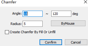
Set parameter angle and radius.
(Optional: ) To automatically add chamfer for closed objects according to the attribute of fill/unfill, check Create Chamfer by Fill or Unfill.
Click Confirm. After setting, the system will automatically add chamfers to the qualified corners.
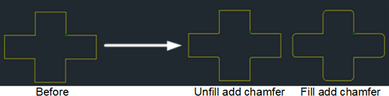
Taking the following as an example, set parameter Angle between 45° and 90° and check Create Chamfer by Fill or Unfill. The effect picture is as follows:
Manual Chamfer
Operation Steps:
You do not need to select an object. In the Tech area of the Common menu bar, click
to open the Chamfer dialog box:Set the radius of the chamfer.
(Optional: ) Check Create Chamfer by Fill or Unfill.
Click By Mouse, and the cursor becomes to
 .
.Move the mouse to the target position and left click to select an adding position.
Right click to exit manually add chamfer function.
When Create Chamfer by Fill or Unfill is not checked, effect picture:

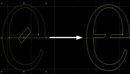
Bridge
When a part is composed of multiple parts, use this function to connect these parts, so that they will not fall off after cutting, and reduce the number of pierces. Using the Bridge function for many times can achieve the effect of completing all graphics at one time. It is mostly used to connect text strokes.
Operation Steps:
In the Software Main Interface, select the graphic.
Note
If the bridged object is text, make sure that the text has been converted to graphics.
In the Tech area of the Common menu bar, click
 to open the Bridge dialog box:
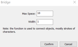
Set parameter Max Space and Width.
Click Confirm.
Click the left mouse button to select the two ends of the bridge.
Right click or press Esc to exit bridge function.
Effect picture:
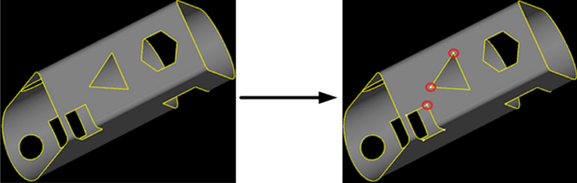
Cooling Point
Add a cooling point at the inflection point of the graphic, and only blow air without turn on the laser. Avoid slowing down at the corners of the graphic during machining, resulting in excessive local laser energy. If continuous machining occurs, such phenomena as corner burning and excessive slag will occur.
The following two methods to add cooling points are supported:
Automatically add cooling point: Automatically add cooling points to selected and qualified objects according to the set value.
Manually add cooling point: The position of inflection point shall be selected by yourself. Angle range: 0 °~180 °.
Note
Cooling point cannot be added at the start point of machining.
Automatic Cooling Point
Operation Steps:
Select the object.
In the Tech area of the Common menu bar, click
 to open the Cooling Point dialog box:
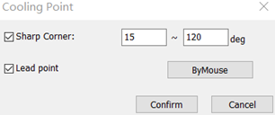
Check Sharp Corner and set the angle range for sharp corner.
(Optional: ) To add a cooling point at the position of lead-in line without being limited by the range of the angle of sharp corner, check Lead Point.
After setting, the system will automatic add cooling points at the inflection points that meet the conditions.
When Sharp Corner is set to 15 ° ~90 °, effect picture:
Manual Cooling Point
To manually add cooling points without selecting objects, follow the steps:
In the Tech area of the Common menu bar, click
to open the Cooling Point dialog box:Click By Mouse. The cursor becomes
.Move the mouse to select a cooling position, and click the left mouse button to add a cooling point.
Right click or press Esc to exit manually add cooling point function.
Effect picture:
Unfill/Fill
Unfill is used to keep the outside of the closed graphic during machining. Fill is used to keep the inside of the closed graphic during machining.
Operation Steps:
Select the closed graphic.
Select one of the following methods to set the unfill and fill cutting:
In the Tech area of the Common menu bar, click
 → Unfill / Fill.
Right click and click Unfill/Fill → Unfill / Fill / Auto Setting.
Note
Automatic setting refers to the setting of unfill or fill according to the nesting relationship of the selected graphic.
Direction
Used to change the original machining path direction in the tool path.
Operation Steps:
Select the object.
Select the following method to open the Machining Direction dialog box:
In the Tech area of the Common menu bar, click
 → Auto Setting.
Right click and click Machining Direction → Set.
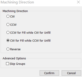
In the Machining Direction area, select the machining direction.
If you only need to reverse the machining direction, select the following method:
In the Tech area of the Common menu bar, click
→ Reverse.Right click and click Machining Direction → Reverse.
In the Machining Direction dialog box, click Reverse.
(Optional: ) If need is setting the machining direction, the primitive machining direction in the group remains unchanged. Check Skip Groups.
After setting, the machining direction is automatically generated.
Centering Mark
When the tube is long, there will be some bending deformation in the middle of the front and rear chucks, resulting in that after cutting a section of length, the centering data executed before machining cannot continue to apply. This operation can eliminate this error. After cutting a certain length, the tube will be automatically leveled and divided, and then the breakpoint resume will be automatically performed.
Operation Steps:
In the Tech area of the Common menu bar, click
 → Manually / Manually (Single Face) / Automatically:
- Manually: Specify the centering position of the tube section at this position.
- Manually (single face): Specifies the centering position of the pipe single face.
- Automatically: After setting the centering mark interval, the system automatically adds the leveling center mark according to the set interval.
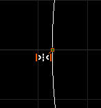
After selecting the marking method, the system automatically adds the centering mark and centering at the specified place. Effect picture:
Inner Compensation
When performing the intersection with a certain angle of inclination, it is impossible to ensure the insertion of the inner diameter of the main tube because the laser head is cut vertically. The Inner Compensation function ensures that the inner diameter of the inserted main tube and the weld are as small as possible.
Note that 2D editing and drawing graphics cannot add inner compensation.
Operation Steps:
Select the object.
Select any of the following methods to open the Inner Compensation dialog box:
In the Tech area of the Common menu bar, click
 .
.Right click and click Inner Compensation.
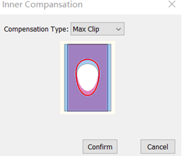
Click the Compensation Type drop-down box to select a compensation type.
According to the compensation method, the effect diagram of setting inner diameter compensation is as follows. The red line is the cutting path:
Max Clip:

Inner Clip:
Min Clip:

Weld Compensation
Used to compensate for weld shrinkage caused by welding.
Operation Steps:
Select any of the following methods and use the Weld Compensation function:
In the Tech area of the Common menu bar, click
 drop down box.
Right click and click Weld Compensation.
Select the setting method in the submenu:
To set the selected break line, click Compensation Select.
To set all break lines, click Compensation All.
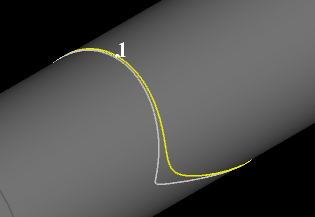
Effect picture:
Vertical Intersection
During cutting, the general intersecting cutting may cause the outside of the cutting hole to be large and the inside to be small, and it is impossible to insert the tube that conforms to the outside frame of the hole. The function of Vertical Intersection can ensure the consistency of the size of internal and external cutting holes.
The following methods are supported:
Vertical angle intersection: According to the normal cut of the vertical intersection of the respective primitives, set the intersection angle by custom.
Set angle intersection: Primitive is cut by normal intersection at the same angle, and the following settings can be selected:
- Vertical intersection: Automatic setting of intersection angle, 0 ° or 180 ° intersection.
- Horizontal intersection: Automatic setting of intersection angle, 90 ° or 270 °.
- Custom intersection: Custom angle, parameter range: 0°-360°.
Prerequisite:
Mark sure:
The current cutting tube is rectangular tube, circular tube, elliptical tube or waist tube.
The target object is non dot, text, scan group, and primitive that bypasses the entire tube by 180 °.
Operation Steps:
Select the object.
Select one of the following methods to set the vertical intersection.
- In the Tech area of the Common menu bar, click
 → select the intersection method.
 - Right click and click Vertical Intersection → select the intersection method.
- In the Tech area of the Common menu bar, click
Perform different operations according to different intersection methods.
If you select Set Vertical Angle Insert, the selected graphics will become white.
If you select Set Regular Angle Insert, then in the pop-up dialog box, check the strategy as required:
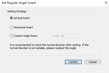
If Show Normal is not checked in the view page, a prompt will pop up indicating whether to show the normal.
Over Arris Jiggle
By adjusting the over arris start stop position. To solve the problem that the actual thickness of the over arris area needs to be cut becomes larger and cannot be completely cut to the deviation between the tube drawing and the actual size of the tube or the deformation of the actual tube during machining.
Before setting over arris jiggle, you can click View → Show Normal in the View area of the menu bar.
Operation Steps:
In the Tech area of the Common menu bar, click
 to open the Over Arris Jiggle dialog box:
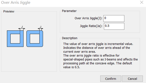
Set parameters Over Arris Jiggle and Jiggle Ratio.
Truncation Line Setting
Set the selected truncation line, where the upper truncation line represents the part, and the lower truncation line represents the scrap.
Operation Steps:
In the 2D Edit interface, select one or more truncation lines.
In the Tech area of the Common menu bar, click
 → select function.
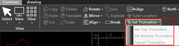
Instant Setting
It is used to set unfill/fill, lead line, machining direction, machining order and kerf compensation with one click, so as to improve machining efficiency.
Operation Steps:
Select one or more objects.
Select any of the following methods to open the Instant Setting dialog box:
In the Tech area of the Common menu bar, click
 .
.Right click and click Instant Setting.

Set as required.
Clear
It is used to clear some set technics.
The clearing items include the following:
Micro joint
Chop
Lead line
Cooling point
Kerf compensation
Inner compensation
Weld compensation
Vertical intersection
Corner chop
Centering mark
Operation Steps:
Select one or more objects.
Select the following methods to clear the technic:
In the Tech area of the Common menu bar, click
 Clear to select the items to be cleared.
Right click and click Clear to select the items to be cleared.