Calibrate B-axis Center
Calculate the mechanical coordinate value of the rotation shaft center through the calibration action. This function is only needed to recalibrate the B-axis center after initial use or mechanical deviation.
Because different machining actions require different centers, the system provides two calibration methods and can use up to two B-axis centers at the same time:
- Standard: It is used to calibrate the B-axis center during ordinary machining.
- Special: It is used to calibrate the B-axis center for special machining actions. Multiple commonly used B-axis centers can be set and named. When in use, it can be configured according to requirements.
Prerequisite:
Before calibrate the B-axis center, ensure that:
The X-axis has returned to the mechanical origin.
For details, see Execute Return to Mechanical Origin.
The tube size parameter settings are the same as the actual tube.
For details, see Set Tube Size.
Operation Steps:
Clamp a standard rectangular tube without chamfer.
Ensure that the clamping state of the rectangular tube is close to horizontal, and move the cutting head to the upper part of the tube.
In the menu bar, click Machining →
 to open the Calibrate B-axis Center dialog box:
In the Standard area, click Calibrate. After calibration, the calibration results will be displayed in the Standard area.
If you are not satisfied with the measurement results, click Center (Z-axis) or Center (X-axis) in the Standard area to manually enter the coordinates.
(Optional: ) If there are special B-axis center requirements, perform the following operations:
In the Special drop-down box, select the item to be set.
(Optional: ) Click Rename to modify the name. Click Rename to rename the set item for easy identification.
In the Special area, click Calibrate. After calibration, the calibration results will be displayed in the Special area.
If you are not satisfied with the measurement results, click Center (Z-axis) or Center (X-axis) in the Special area to manually enter the coordinates.
You can also click Copy to copy the calibration center in the standard area to the special area, and then modify it.
Click Advanced Setting to set the rotation center of Normal and Feed Cutting in the pop-up Advanced Setting dialog box.
Check Special B-axis Rotary Center. During machining, the center of B-axis adopts the strategy in Advanced Setting.
If it is not checked, the center of B-axis uses the coordinates set in the Standard area during machining.
Input the edge exit speed followed by the cutting head in the Out-margin Speed input box.
Click Confirm.
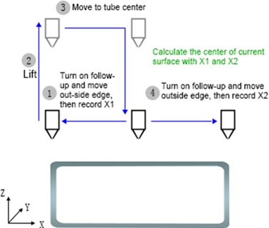
The system starts to perform the calibration action:
Leveling tube:

Find the B-axis center:
Take one side of the tube as an example: