Set Drive Parameters
Basic drive parameters need to be set before the drive can start driving machining movement.
Different control systems require different settings.
Set Drive Parameters in Non-bus Control Systems
Different servo drive parameters need to be set in different follow control modes:
- Set Drive Parameters in Position Loop Control Mode
- Set Drive Parameters in Velocity Loop Control Mode
If you are using a non-WEIHONG drive (WISE):
Ensure that the servo drive SON signal is active low (ON when connected to GND of a 24V power supply).
If the servo drive is active low when it works normally, set the polarity of the drive alarm input port to NC. If the servo drive is active low when it reports an alarm, set the polarity of the drive alarm input port to NO.
Set the drive pulse signal type parameter to pulse + direction.
Ensure that the servo drive does not have an external emergency stop signal input port. If it does, check the signal logic.
Ensure that the terminal board is connected to a 24V power supply before drive trial run.
Set Drive Parameters in Position Loop Control Mode
Test parameter settings in position loop control mode as shown below:
- WISE
- Yaskawa Σ-Ⅱ
- Yaskawa Σ-Ⅱ Σ-Ⅴ / Σ-7
- Panasonic MINAS A4
- Panasonic MINAS A5
- Fuji FALDIC-β
- Fuji ALPHA 5
- Delta ASDA-A
- Delta ASDA-A2
- Delta ASDA-B
- Delta ASDA-B2
WISE
The parameters and descriptions are shown below:
Pr001 Control mode selection
- Description: Control mode setting
- Unit: -
- Range
- 1: Position control mode
- 2: Velocity control mode
- Value: 1
Pr528 LED initial state
- Description: Pulse detection is used in WEIHONG control systems to check to see if correct pulses are sent and determine if there is electric interference.
- Unit: -
- Range: -
- Value: 6 Command pulse sum
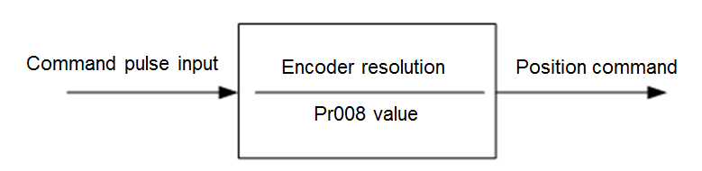
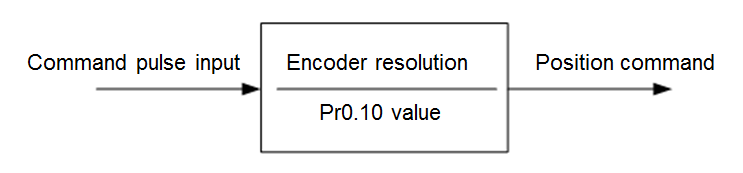
Pr008 Number of command pulses per motor turn
- Description: The number of command pulses for the motor to rotate by one turn
- Unit: -
- Range
- 0: Pr009 and Pr010 are effective
- Not 0: Pr008 = Screw pitch/(pulse equivalent * mechanical reduction ratio)
- Value: 0
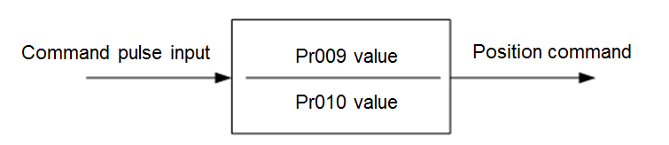
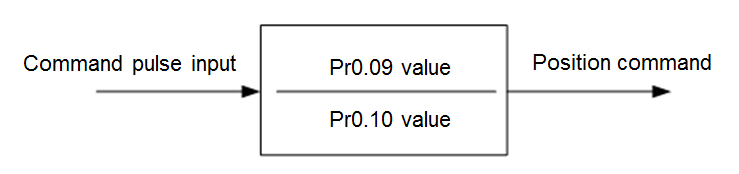
Pr009 1st command division and multiplication (numerator), Pr010 Command division and multiplication (denominator)
- Description: Pay attention to the ratio between Pr009 and Pr010.
- Unit: -
- Range: 0–230
- Value: If screw pitch = 5 mm, encoder resolution = 10000, directly connected to the coupler, pulse equivalent = 0.001 mm: Pr009 = 10000, Pr010=screw pitch / pulse equivalent=5000, which means Pr009/Pr010 = 10000/5000=2/1.
Pr011 Number of pulses output by one motor turn
- Description: Number of pulses output by one motor turn
- Unit: -
- Range: -
- value: If pulse equivalent = 0.001, there is no speed reducer, screw pitch = 10 mm: Pr011=2500; if screw pitch = 5 mm: Pr011 = 1250
Pr100 1st position loop gain
- Description: 1st position loop gain
- Unit: 0.1/s
- Range: -
- Value: 480 (default) or subject to actual situation.
Pr101 1st velocity loop gain
- Description: 1st velocity loop gain
- Unit: 0.1 Hz
- Range: -
- Value: 270 (default) or subject to actual situation.
Pr102 1st velocity loop integral time constant
- Description:1st velocity loop integral time constant
- Unit: 0.1 ms
- Range: -
- Value: 210 (default) or subject to actual situation.
Relationship between Pr008, Pr009, and Pr010
Pr009 and Pr010 values are not valid. System processing is based on the Pr008 value.
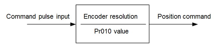
If Pr008 and Pr009 are 0, system processing is based on the Pr010 value.
If Pr008 is 0, and Pr009 and Pr010 values are not valid:
Yaskawa Σ-Ⅱ
The parameters and descriptions are shown below:
Fn010 Password setting (preventing random parameter modification)
- Description: Password setting (preventing random parameter modification)
- Unit: -
- Range
- If Fn010 is set to 0000, modification of user parameters (PnXXX) and some auxiliary function parameters (FnXXX) is allowed.
- If Fn010 is set to 0001, modification of user parameters (PnXXX) and some auxiliary function parameters (FnXXX) is not allowed.
- Value: 0000
Un00C Input command pulse counter
- Description: Pulse detection is used in WEIHONG control systems to check to see if correct pulses are sent and determine if there is electric interference.
- Unit: -
- Range: -
- Value: In hexadecimal, low-order (L) 4 digits
Pn000 Rotation direction and control mode selection
- Direction: Rotation direction and control mode selection
- Unit: -
- Range
- 0: The motor rotates CW (anti-clockwise when observing from the load/lead screw side).
- 1: The motor rotates CCW. The control mode is position control. Always calculates pulse commands.
- Value: 0010
Pn200 Pulse command format selection
- Description: Pulse command format selection
- Unit: -
- Range
- Digit 0: If digit 0 is set to 5, the command is pulse + direction, negative logic.
- Digit 3: If digit 3 is set to 0, the differential signal goes into the filter.
- Value: 0005
Pn50A Function selection
- Description: Function selection
- Unit: -
- Range
- Digit 1: If digit 1 is set to 0, the /S-ON signal is enabled and its input pin is No.40. If digit 1 is set to 7, the /S-ON signal is always ON.
- Digit 3: If digit 3 is set to 8, the CW input inhibition signal P-OT will not be used.
- Value: 8100
Pn50B Function selection
- Description: Function selection
- Unit: -
- Range: Digit 0: If digit 0 is set to 8, the CCW input inhibition signal N-OT will not be used.
- Value: 6548
Pn50F Function selection
- Description: Applicable when the servo motor has a brake.
- Unit: -
- Range: Digit 2: If digit 2 is set to 3, CN1-29 and 30 output brake interlocking signal/BK to control the 24V relay for brake.
- Value: 0300
Pn50E Function selection
- Description: Applicable when the servo motor has a brake.
- Unit: -
- Range: None of the four digits can be set to 3 in case that CN1-29 and CN1-30 are used for other functions, causing braking failure.
- Value: 0211
Pn506 Brake delay when servo motor is off
- Description: Applicable when the servo motor has a brake.
- Unit: 10 ms
- Range: -
- Value: Subject to actual situation.
Pn202 Electronic gear ratio numerator, Pn203 Electronic gear ratio denominator
- Description: Relation between Pn202 and Pn203
- Unit: 10 ms
- Equation:
- Pn202 = Pulse number per encoder turn × 4 × Mechanical deceleration rate
- Pn203 = Screw pitch/ Pulse equivalent
- Range: -
- Value
- When screw pitch = 5 mm, the encoder is 17 digits, axis coupling joint is used, pulse equivalent = 0.001 mm: Pn202=16384 and Pn203=625
- When screw pitch = 5 mm, the encoder is 17 digits, axis coupling joint is used, pulse equivalent = 0.0005 mm: Pn202=8192 and Pn203=625
Yaskawa Σ-Ⅴ/Σ-7
The parameters and descriptions are shown below:
Fn010 Parameter input inhibition setting
- Description: Parameter input inhibition setting
- Unit: -
- Range
- If Fn010 is set to 0000, modification of user parameters (PnXXX) and some auxiliary function parameters (FnXXX) is allowed.
- If Fn010 is set to 0001, modification of user parameters (PnXXX) and some auxiliary function parameters (FnXXX) is not allowed.
- Value: 0000
Pn000 Function selection basic switch 0
- Description: Function selection basic switch 0
- Unit: -
- Range
- Digit 0: If digit 0 is set to 0, the motor rotates CW after receiving CW commands.
- Digit 1: If digit 1 is set to 1, the control mode is position control (pulse sequence commands).
- Value: 0010
Pn200 Position control command format selection switch
- Description: Position control command format selection switch
- Unit: -
- Range: If digit 0 is set to 5, the command format is pulse + direction, negative logic.
- Value: 0005
Pn50A Input signal selection 1
- Description: Input signal selection 1
- Unit: -
- Range
- Digit 1: If digit 1 is set to 0, /S-ON signal is enabled and its input pin is No.40. If digit 1 is set to 7, the servo drive is always ON.
- Digit 3: If digit 3 is set to 8, the CW input inhibition signal P-OT will not be used.
- Value: 8100
Pn50B Input signal selection 2
- Description: Input signal selection 2
- Unit: -
- Range: If digit 0 is set to 8, the CCW input inhibition signal N-OT will not be used.
- Value: 6548
Pn50F Output signal selection 2
- Description: Applicable when the servo motor has a brake.
- Unit: -
- Range: If digit 2 is set to 3, CN1-29 and 30 output brake interlocking signal/BK to control the 24V relay for brake.
- Value: 0300
Pn50E Output signal selection 1
- Description: Applicable when the servo motor has a brake.
- Unit: -
- Range: None of the four digits can be set to 3 in case that CN1-29 and CN1-30 are used for other functions, causing braking failure.
- Value: 0211
Pn506 Brake command: Servo OFF delay
- Description: Applicable when the servo motor has a brake.
- Unit: ms
- Range: -
- Value: Subject to actual situation.
Pn20E Electronic gear ratio numerator, Pn210 Electronic gear ratio denominator
- Description: Relation between Pn20E and Pn210
- Unit: -
- Equation: Pn20E/Pn210 = (Encoder resolution × pulse equivalent × mechanical reduction ratio)/screw pitch
- Range: -
- Value: Manual calculation
Pn212 Encoder allocated pulse number
- Description: Encoder allocated pulse number
- Unit: -
- Range:24–230
- Value: When pulse equivalent = 0.001, there is no reducer, and screw pitch = 10 mm, Pn212 = 2500; when screw pitch = 5 mm, Pn212 = 1250
Panasonic MINAS A4
The parameters and descriptions are shown below:
Pr01 LED initial state
- Description: Pulse detection is used in WEIHONG control systems to check to see if correct pulses are sent and determine if there is electric interference.
- Unit: -
- Range: -
- Value: 15
Pr02 Control mode selection
- Description: Control mode selection
- Unit: -
- Range
- 0: Position control
- 1: Velocity control
- 2: Torque control
- Value: 0
Pr40 Command pulse input selection
- Description: Command pulse input selection
- Unit: -
- Range: 1: input via dedicated differential circuit.
- Value: 1
Pr42 Command pulse input format selection
- Description: Command pulse input format selection
- Unit: -
- Range: 3: The command pulse input format is pulse + direction, negative logic
- Value: 3
Pr44 Feedback pulse division and multiplication numerator
- Description: Feedback pulse division and multiplication numerator
- Unit: -
- Range: 1–32767
- Typical value: When pulse equivalent = 0.001, there is no reducer, and screw pitch = 10 mm, Pr44 = 2500; when screw pitch = 5 mm, Pr44 = 1250
Pr48 Command pulse division and multiplication 1st numerator, Pr4B Command pulse division and multiplication denominator
- Description: Relation between Pr48 and Pr4B
- Unit: -
- Range: 1–10000
- Value: When screw pitch = 5 mm, the encoder resolution is 10000, axis coupling joint is used, and pulse equivalent = 0.001 mm: Pr48= 10000, Pr4B= screw pitch/pulse equivalent = 5/0.001=5000. Pr48/Pr4B=10000/5000=2/1.
Panasonic MINAS A5
The parameters and descriptions are shown below:
Pr5.28 LED initial state
- Description: Pulse detection is used in WEIHONG control systems to check to see if correct pulses are sent and determine if there is electric interference.
- Unit: -
- Range: -
- Value: 6
Pr0.01 Control mode setting
- Description: Control mode setting
- Unit: -
- Range
- 0: Position control.
- 1: Velocity control.
- 2: Torque control.
- Value: 0
Pr0.05 Command pulse input selection
- Description: Command pulse input selection
- Unit: -
- Range
- 0: Opto-electronic coupler input (PULS1, PULS2, SIGN1, SIGN2)
- 1: Dedicated line drive input (PULSH1, PULSH2, SIGNH1, SIGNH2)
- Value: 1 (in common cases)
Pr0.07 Command pulse input format selection
- Description: Command pulse input format selection
- Unit: -
- Range: 3: the command pulse input format is pulse + direction, negative logic
- Value: 3
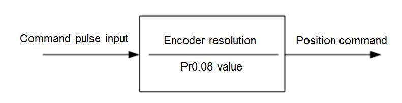
Pr0.08 Number of command pulses per turn
- Description: Number of command pulses per turn
- Unit: -
- Range
- If Pr0.08 is set to 0, Pr0.09 and Pr0.10 are valid.
- If Pr0.08 is not 0, Pr0.08 = screw pitch/(pulse equivalent × mechanical reduction ratio)
- Value: 0
Pr0.09 1st command division and multiplication numerator, Pr0.10 Command pulse division and multiplication denominator
- Description: Relation between Pr0.09 and Pr0.10
- Unit: -
- Range: 0–230
- Value: When screw pitch = 5 mm, the encoder resolution is 10000, axis coupling joint is used, and pulse equivalent = 0.001 mm: Pr0.09=10000 and Pr0.10=screw pitch/pulse equivalent=5/0.001=5000. Pr0.09/Pr0.10=10000/5000=2/1.
Pr0.11 Number of pulse output by one motor turn
- Description: Number of pulse output by one motor turn
- Unit: -
- Range: 1–262144
- Value: When pulse equivalent = 0.001, there is no reducer, and screw pitch = 10 mm, Pr0.11 = 2500; when screw pitch = 5 mm, Pr0.11 = 1250
Relation between Pr0.08, Pr0.09, and Pr0.10 values
Pr0.09 and Pr0.10 values are not valid. System processing is based on the Pr0.08 value.
If Pr0.08 and Pr0.09 are 0, system processing is based on the Pr0.10 value.
If Pr0.08 is 0 but Pr0.09 is not 0, system processing is based on the Pr0.09 and Pr0.10 values.
Fuji FALDIC-β
The parameters and descriptions are shown below:
Command pulse numerator α, 02 Command pulse denominator β
- Description: Stand for electronic gear ratio numerator and denominator.
- Unit: -
- Range: 1–32767
- Equation: α/β = (encoder resolution × pulse equivalent × mechanical reduction ratio)/screw pitch
- Value: When encoder resolution = 65536, pulse equivalent = 0.001, screw pitch = 5 mm, and mechanical reduction ratio = 1: α/β=65536×0.001/5=8192/625, which means α=8192 and β=625.
Pulse train input format
- Description: Pulse train input format
- Unit: -
- Range: 0: The pulse train input format is pulse + direction (symbol), negative logic
- Value: 0
Rotation direction
- Description: Rotation direction
- Unit: -
- Range
- 0: Rotates CW (anti-clockwise when observing from the load side)
- 1: Rotates CCW (clockwise when observing from the load side)
- Value: 0 or 1
CONT1 signal distribution
- Description: CONT1 signal distribution
- Unit: -
- Range: 1: CONT1 is distributed to RUN (SON). If CONT1 is not distributed, it becomes ON if there is no alarm after power-on.
- Value: 1
CONT2 signal distribution
- Description: CONT2 signal distribution
- Unit: -
- Range: 2: CONT2 is distributed to RST (CLR: servo alarm clearing). Parameter 12, 13, and 14 are 0, which means that CONT3, CONT4, and CONT5 cannot be distributed to OT (overtravel) or EMG (external emergency stop).
- Value: 2
OUT1 signal distribution
- Description: OUT1 signal distribution
- Unit: -
- Range
- 1: OUT1 is distributed to alarm output contact a, which is normally open.
- 2: OUT1 is distributed to alarm output contact b, which is normally closed.
- Value: 1
Parameter modification inhibition
- Description: Parameter modification inhibition
- Unit: -
- Range
- 0: Drive parameter values can be modified.
- 1: Drive parameter values cannot be modified.
- Value: 0 or 1
CONT 1 constant validity 1
- Description: CONT 1 constant validity 1
- Unit: -
- Range: 1: valid upon servo motor start (RUN).
- Value: 1
Fuji ALPHA 5
The parameters and descriptions are shown below:
PA1_01 Control mode selection
- Description: PA1_01 control mode selection
- Unit: -
- Range
- 0: Position control.
- 1: Velocity control.
- Value: 0
PA1_06 Electronic gear ratio numerator 0, PA1_07 Electronic gear ratio denominator
- Description: Relation between PA1_06 and PA1_07
- Unit: -
- Range: 1–32767
- Equation: PA1_06/PA1_07 =(Encoder resolution × pulse equivalent × mechanical reduction ratio)/screw pitch
- Value: When encoder resolution = 65536, pulse equivalent = 0.001, screw pitch = 5 mm, and mechanical reduction ratio = 1: PA1_06/PA1_07 =65536×0.001/5=8192/625. Therefore, PA1_06 = 8192 and PA1_07 = 625.
PA1_03 Command pulse format
- Description: PA1_03 command pulse format
- Unit: -
- Range: 0: The pulse train input format is pulse + direction (symbol), negative logic.
- Value: 0
PA1_04 Rotation direction
- Description: Rotation direction
- Unit: -
- Range
- 0: Rotates CW (anti-clockwise when observing from the load side)
- 1: Rotates CCW (clockwise when observing from the load side)
- Value: 0 or 1
PA3_01 CONT1 signal distribution
- Description:CONT1 signal distribution
- Unit: -
- Range: 1: CONT1 is distributed to RUN (SON). If CONT1 is not distributed, it becomes ON if there is no alarm after power-on.
- Value: 1
PA3_02 CONT2 signal distribution
- Description: CONT2 signal distribution
- Unit: -
- Range 2: CONT2 is distributed to RST (CLR: servo alarm clearing). Parameter 12, 13, and 14 are 0, which means that CONT3, CONT4, and CONT5 cannot be distributed to OT (overtravel) or EMG (external emergency stop).
- Value: 2
PA3_51 OUT1 signal distribution
- Description: OUT1 signal distribution
- Unit: -
- Range
- 16: OUT1 is distributed to alarm output contact a, which is normally open.
- 76: OUT1 is distributed to alarm output contact b, which is normally closed.
- Value: 16
PA3_26 CONT 1 constant validity 1
- Description: CONT 1 constant validity 1
- Unit: -
- Range: 1: valid upon servo motor start (RUN).
- Value: 2
PA1_08 Number of pulse output by one motor turn
- Description: Number of pulse output by one motor turn
- Unit: -
- Range: 16–214
- Typical value: When pulse equivalent = 0.001, there is no reducer, and screw pitch = 10 mm, PA1_08 = 2500; when screw pitch = 5 mm, PA1_08 = 1250
Delta ASDA-A
The parameters and descriptions are shown below:
P0-02 Drive status display
- Description: Pulse detection is used in WEIHONG control systems to check to see if correct pulses are sent and determine if there is electric interference.
- Unit: -
- Format: -
- Range: -
- Value: 02
P1-00 External pulse input format
- Description: External pulse input format
- Unit: -
- Format: ZYX
- X=2: The external pulse input format is pulse + direction, negative logic
- Z=1: negative logic
- Range: -
- Value: 102
P1-01 Control mode setting
- Description: Control mode setting
- Unit: -
- Format: ZYX1X0
- Z=0: DIO value does not change when the control mode is switched. Control mode was not switched; therefore, Z=0.
- Y=0: Rotates CW (anti-clockwise when observing from the load side). Y=1: Rotates CCW.
- X1X0=00: The control mode is position control.
- Range: -
- Value: 0000
P1-32 Motor stopping mode
- Description: Motor stopping mode
- Unit: -
- Format: YX
- Y=0: When the servo motor is disabled, dynamic braking is used. Y=1: When the servo motor is disabled, the motor moves freely.
- X=0: The motor is stopped instantly. X=1: The motor decelerates before stops completely.
- Range: -
- Value: 00
P1-44 Electronic gear ratio numerator N1, P1-45 Electronic gear ratio denominator M
- Description: Relation between P1-44 and P1-45.
- Unit: -
- Format: -
- Range: 1–32767
- Equation: N1/M =(Encoder pulse number × 4 × pulse equivalent × mechanical reduction ratio)/screw pitch.
- Value: When the encoder pulse number = 2500, pulse equivalent = 0.001, screw pitch = 5 mm, and mechanical reduction ratio = 1, N1/M=2500×4×0.001/5=2/1. Therefore, N1=2 and M=1.
P2-10 Digital input pin DI1 function setting
- Description: Digital input pin DI1 function setting
- Unit: -
- Format: X2X1X0
- X1X0=01: Set digital input DI1 to SON, matching pin No.9 of CN1.
- X2=1: Set input DI1 to the normally open contact a.
- Range: -
- Value: 101
P2-15 Digital input pin DI6 function setting and P2-16 Digital input pin DI7 function setting
- Description: DI6 are DI7 are NC position limit signal input by default. The drive cannot work before the CN1 pin No.32 and pin No.31 are connected.
- Unit: -
- Format: P2-15=P2-16=X2X1X0
- X2=1: Set DI6 and DI7 input to the NO contact a.
- X1X0=00: Drive position limit input was not used.
- Range: -
- Value: P2-15=P2-16=100
P2-17 Digital input pin DI8 function setting
- Description: Digital input pin DI8 function setting
- Unit: -
- Format: X2X1X0. X2X1X0=100: External EMG (emergency stop input) was not used.
- Range: -
- Value: 100
P2-21 Digital output pin DO4 function setting
- Description: DO4 pins are pin No.1 and No.26, which are used for Z-axis clamping position braking signals.
- Unit: -
- Format: X2X1X0
- X2=1: Set DO4 output to the NO contact a. X2=1: Set DO4 output to the NC contact b.
- X1X0=08: Set pin No.1 and No.26 to BK+ and BK- respectively.
- Range: -
- Value: 108
P2-22 Digital output pin DO5 function setting
- Description: DO5 pins are pin No.28 and No.27, which are used for servo alarm signals.
- Unit: -
- Format: X2X1X0
- X2=0: Set DO5 output to the NC contact b.
- X1X0=07: Set pin No.28 and No.27 to ALRM+ and ALRM- respectively.
- Range: -
- Value: 007
P2-51 Servo enablement SON setting
- Description: Servo enablement SON setting
- Unit: -
- Format: -
- Range
- 0: Servo motor enablement must be triggered by digital signals.
- 1: Servo motor is automatically enabled after powered on if there is no alarm.
- Value: 0 (1 when SON signal cables are unavailable)
Delta ASDA-A2
The parameters and descriptions are shown below:
P0-02 Drive status display
- Description: Pulse detection is used in WEIHONG control systems to check to see if correct pulses are sent and determine if there is electric interference.
- Unit: -
- Format: -
- Range: -
- Value: 02
P1-00 External pulse input format
- Description: External pulse input format
- Unit: -
- Format: ZYX
- X=2: The external pulse input format is pulse + direction, negative logic
- Z=1: negative logic
- Range: -
- Value: 102
P1-01 Control mode setting
- Description: Control mode setting
- Unit: -
- Format: ZYX1X0
- Z=0: DIO value does not change when the control mode is switched. Control mode was not switched; therefore, Z=0.
- Y=0: Rotates CW (anti-clockwise when observing from the load side). Y=1: Rotates CCW.
- X1X0= 00: The control mode is position control.
- Range: -
- Value: 0000
P1-44 Electronic gear ratio numerator N1 and P1-45 Electronic gear ratio denominator M
- Description: Relation between P1-44 and P1-45
- Unit: -
- Format: -
- Range: 1–32767
- Equation: P1-44/P1-45 = (Encoder resolution × pulse equivalent × mechanical reduction ratio)/screw pitch.
- Value: When the encoder pulse number = 2500, pulse equivalent = 0.001, screw pitch = 5 mm, and mechanical reduction ratio = 1, N1/M=2500×4×0.001/5=2/1. Therefore, N1=2 and M=1.
P1-46 Detector pulse output number setting
- Description: Setting of the revolving single-direction pulse number.
- Unit: -
- Format: -
- Range: 20–320000
- Value: When pulse equivalent = 0.001, there is no reducer, and screw pitch = 10 mm, P1-46 = 10000; when screw pitch = 5 mm, P1-46 = 5000
P2-10 Digital input pin DI1 function setting
- Description: Setting of the revolving single-direction pulse number.
- Unit: -
- Format: X2X1X0
- X1X0=01: Set digital input DI1 to SON, matching pin No.9 of CN1.
- X2=1: Set input DI1 to the normally open contact a.
- Range: -
- Value: 101
P2-15 Digital input pin DI6 function setting
- Description: DI6 are DI7 are NC position limit signal input by default. The drive cannot work before the CN1 pin No.32 and pin No.31 are connected.
- Unit: -
- Format: X2X1X0
- X2=1: Set DI6 and DI7 input to the NO contact a.
- X1X0=00: Drive position limit input was not used.
- Range: -
- Value: 100
P2-16 Digital input pin DI7 function setting
- Description: Digital input pin DI7 function setting
- Unit: -
- Format: X2X1X0
- Range: -
- Value: 100
P2-17 Digital input pin DI8 function setting
- Description: Digital input pin DI8 function setting
- Unit: -
- Format: X2X1X0. X2X1X0=100: External EMG (emergency stop input) was not used.
- Range: -
- Value: 100
P2-21 Digital output pin DO4 function setting
- Description: DO4 pins are pin No.1 and No.26, which are used for Z-axis clamping position braking signals.
- Unit: -
- Format: X2X1X0
- X2=1: Set DO4 output to the NO contact a. X2=1: Set DO4 output to the NC contact b.
- X1X0=08: Set pin No.1 and No.26 to BK+ and BK- respectively.
- Range: -
- Value: 108
P2-22 Digital output pin DO5 function setting
- Description: DO5 pins are pin No.28 and No.27, which are used for servo alarm signals.
- Unit: -
- Format: X2X1X0
- X2=0: Set DO5 output to the NC contact b.
- X1X0=07: Set pin No.28 and No.27 to ALRM+ and ALRM- respectively.
- Range: -
- Value: 007
Delta ASDA-B
The parameters and descriptions are shown below:
P0-02 Drive status display
- Description: Pulse detection is used in WEIHONG control systems to check to see if correct pulses are sent and determine if there is electric interference.
- Unit: -
- Format: -
- Range: -
- Value: 02
P1-00 External pulse train input format
- Description: Setting of external pulse train input format
- Unit: -
- Format: ZYX
- X=2: The external pulse input format is pulse + direction, negative logic
- Z=1: negative logic1
- Range: -
- Value: 102
P1-01 Control mode setting
- Description: Control mode setting
- Unit: -
- Format: YX1X0
- Y=0: Rotates CW (anti-clockwise when observing from the load side). Y=1: Rotates CCW.
- X1X0=00: The control mode is position control.
- Range: -
- Value: 000
P1-32 Motor stopping mode
- Description: Motor stopping mode
- Unit: -
- Format: YX
- Y=0: When the servo motor is disabled, dynamic braking is used. Y=1: When the servo motor is disabled, the motor moves freely.
- X=0: The motor is stopped instantly. X=1: The motor decelerates before stops completely.
- Range: -
- Value: 00
P1-44 Electronic gear ratio numerator N1 and P1-45 Electronic gear ratio denominator M
- Description: Relation between P1-44 and P1-45
- Unit: -
- Format: -
- Range: 1–32767
- Equation: P1-44/P1-45 = (Encoder resolution × pulse equivalent × mechanical reduction ratio)/screw pitch.
- Value: When the encoder pulse number = 2500, pulse equivalent = 0.001, screw pitch = 5 mm, and mechanical reduction ratio = 1, N1/M=2500×4×0.001/5=2/1. Therefore, N1=2 and M=1.
P2-10 Digital input pin DI1 function setting
- Description: Digital input pin DI1 function setting
- Unit: -
- Format: X2X1X0
- X1X0=01: Set digital input DI1 to SON, matching pin No.17 of CN1.
- X2=1: Set input DI1 to the normally open contact a.
- Range: -
- Value: 101
P2-15 Digital input pin DI6 function setting
- Description: DI6 is NC position limit signal input by default. The drive cannot work before the CN1 pin No.32 and pin No.31 are connected.
- Unit: -
- Format: X2X1X0
- X2=1: Set input DI6 to the normally open contact a.
- X1X0=00: Drive position limit input was not used.
- Range: -
- Value: 100
P2-18 Digital output pin DO1 function setting
- Description: DO1 pin is pin No.16, which is used for Z-axis clamping position braking signals.
- Unit: -
- Format: X2X1X0
- X2=1: Set DO1 output to the NO contact a. X2=0: Set DO4 output to the NC contact b.
- X1X0=08: Set pin No.16 to BK+.
- Range: -
- Value: 108
P2-20 Digital output pin DO3 function setting
- Description: DO3 pin is pin No.1, which is used for servo alarm signals.
- Unit: -
- Format: 2X1X0
- X2=0: Set DO3 output to the NC contact b.
- X1X0=07: Set pin No.1 to ALRM+.
- Range: -
- Value: 007
Delta ASDA-B2
The parameters and descriptions are shown below:
P0-02 Drive status display
- Description: Pulse detection is used in WEIHONG control systems to check to see if correct pulses are sent and determine if there is electric interference.
- Unit: -
- Format: -
- Range: -
- Value: 02
P1-00 External pulse train input format
- Description: Setting of external pulse train input format
- Unit: -
- Format: ZYX
- X=2: The external pulse input format is pulse + direction, negative logic
- Z=1: negative logic
- Range: -
- Value: 102
P1-01 Control mode setting
- Description: Control mode setting
- Unit: -
- Format: ZYX1X0
- Z=0: DIO value does not change when the control mode is switched. Control mode was not switched; therefore, Z=0.
- Y=0: Rotates CW (anti-clockwise when observing from the load side). Y=1: Rotates CCW.
- X1X0=00: The control mode is position control.
- Range: -
- Value: 0000
P1-44 Electronic gear ratio numerator N1 and P1-45 Electronic gear ratio denominator M
- Description: Relation between P1-44 and P1-45
- Unit: -
- Format: ZYX1X0
- Z=0: DIO value does not change when the control mode is switched. Control mode was not switched; therefore, Z=0.
- Y=0: Rotates CW (anti-clockwise when observing from the load side). Y=1: Rotates CCW.
- X1X0=00: The control mode is position control.
- Range: 1–32767
- Equation: P1-44/P1-45 = (Encoder resolution × pulse equivalent × mechanical reduction ratio)/screw pitch.
- Value: When the encoder pulse number = 2500, pulse equivalent = 0.001, screw pitch = 5 mm, and mechanical reduction ratio = 1, N1/M=2500×4×0.001/5=2/1. Therefore, N1=2 and M=1.
P1-46 Detector pulse output number setting
- Description: Setting of the revolving single-direction pulse number.
- Unit: -
- Format: -
- Range: 20–40000
- Value: When pulse equivalent = 0.001, there is no reducer, and screw pitch = 10 mm, P1-46 = 10000; when screw pitch = 5 mm, P1-46 = 5000
P2-10 Digital input pin DI1 function setting
- Description: Digital input pin DI1 function setting
- Unit: -
- Format: X2X1X0
- X1X0=01: Set digital input DI1 to SON, matching pin No.9 of CN1.
- X2=1: Set input DI1 to the normally open contact a.
- Range: -
- Value: 101
P2-15 Digital input pin DI6 function setting
- Description: DI6 are DI7 are NC position limit signal input by default. The drive cannot work before the CN1 pin No.32 and pin No.31 are connected.
- Unit: -
- Format: X2X1X0
- X2=0: Set DI6 and DI7 input to the NC contact b.
- X1X0=00: Drive position limit input was not used.
- Range: -
- Value: 000
P2-16 Digital input pin DI7 function setting
- Description: Digital input pin DI7 function setting
- Unit: -
- Format: X2X1X0
- Range: -
- Value: 000
P2-17 Digital input pin DI8 function setting
- Description: Digital input pin DI8 function setting
- Unit: -
- Format: X2X1X0. When X2X1X0=000: External EMG (emergency stop input) was not used.
- Range: -
- Value: 000
P2-18 Digital output pin DO1 function setting
- Description: DO1 pins are pin No.6 and No.7, which are used for Z-axis clamping position braking signals.
- Unit: -
- Format: X2X1X0
- X2=1: Set DO1 output to the NO contact a. X2=1: Set DO4 output to the NC contact b.
- X1X0=08: Set pin No.6 and No.7 to BK- and BK+ respectively.
- Range: -
- Value: 108
P2-22 Digital output pin DO5 function setting
- Description: DO5 pins are pin No.28 and No.27, which are used for servo alarm signals.
- Unit: -
- Format: X2X1X0
- X2=0: Set DO5 output to the NC contact b.
- X1X0=07: Set pin No.28 and No.27 to ALRM+ and ALRM- respectively.
- Range: -
- Value: 007
Set Drive Parameters in Velocity Loop Control Mode
Test parameter settings in velocity loop control mode as shown below:
- WISE
- Yaskawa Σ- 7
- Panasonic MINAS A5
- Fuji ALPHA 5
To make the motor output rated rotational speed under 10V voltage in velocity loop control mode, parameters need to be set differently from that in position loop control mode, as shown below (taking a screw pitch of 10 mm as an example):
| Parameter | WISE | Yaskawa Σ- 7 | Panasonic MINAS A5 | Fuji ALPHA 5 |
|---|---|---|---|---|
| Control mode selection | Pr001=2 | Pn000=0 | Pr0.01=1 | PA1_01=1 |
| Command pulse number | Pr011=2500 | Pn212=2500 | Pr011=2500 | PA1_08=250 |
| Motor rotational speed under 10V | Pr302=300 | Pn300=1000 | Pr3.02=300 | PA3-31=10 |
The parameter Motor rotational speed under 10V is available only in velocity loop control mode.
Set Drive Parameters in Bus Control Systems
Parameter setting methods vary based on the servo drive brand. This section mainly introduces how to set basic parameters and station addresses of WISE drive and Yaskawa ∑5 / ∑7 drives.
Set Common Drive Parameters
Two methods are available for you to set the drive parameters:
Drive front panel. For details, see the drive user manual.
NcEditor software.
Follow the steps below to set drive parameters in NcEditor:
In the menu, click System > Drive Parameters to open the Driver Param window:
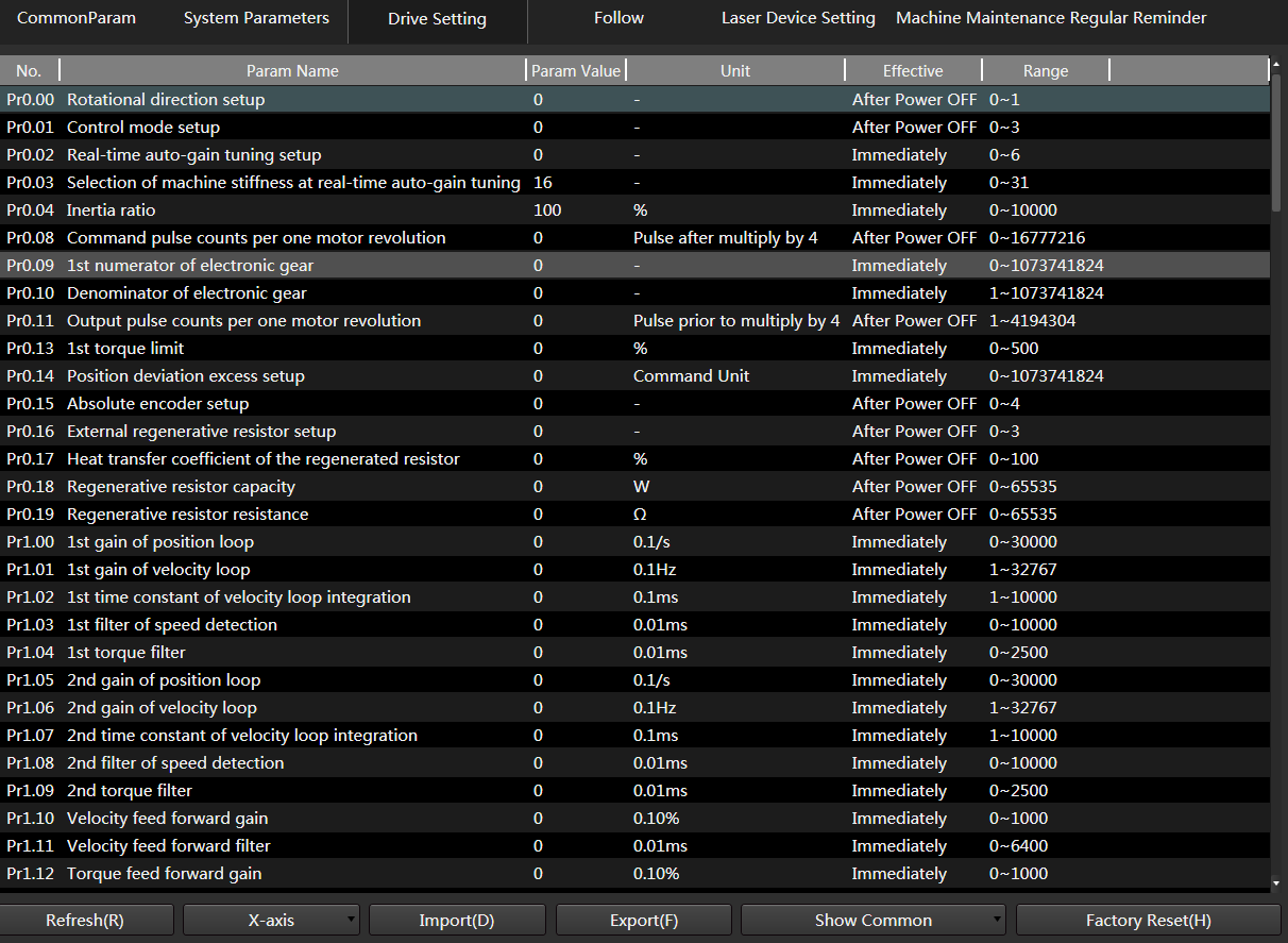
Click Refresh to update the drive parameters.
Double-click the target parameter to set it.
Basic parameters that need setting in NcEditor are shown below. Refer to the user manual of the drive brand to set other parameters.
Yaskawa drives:
- Pn00B function selection basic switch B: 0000 (three-phase)/0100 (single-phase)
- Pn50A input signal selection 1: 8881
- Pn50B input signal selection 2: 8888
- Pn50E output signal selection 1: 0000
- Pn50F output signal selection 2: 0100
- Pn510 output signal selection 3: 0000
- Pn514 output signal selection 4: 0000
WISE drives: Pr001 Control mode setting: 1 (position control)
Set Station Address
By setting the station address, information can be transferred between the software, Lambda controller, and drive.
Station address of each axis drive is unique and has to be consistent with the value of the corresponding station address parameter in NcEditor for V15. If its station address parameter is set to 0, the communication function is disabled.
Set Station Address for Yaskawa Drives
Set the station addresses for Yaskawa drives by using two types of switches on the drive:
Flip switches: Four small switches numbered 1–4 for setting of ON/OFF.
Rotation switch: Rotate the switch to select from 0–9.
Follow the steps below to set station addresses for Yaskawa drives:
Set flip switch 1–4 to ON, ON, OF, and OFF respectively to enable bus functions.
Rotate the rotation switch to select a number as the station address.
Note: Select station addresses for the axes in sequence (for example, 1 for X axis, 2 for Y axis, and 3 for Z axis, etc.).
Open NcEditor. Set the axis station address parameters to the values set by the drive rotation switch.
Set Station Address for WISE Drives
Set the station addresses for WISE drives by using the drive front panel.
Follow the steps below to set station addresses for WISE drives:
Set Pr001 Control mode setting to 1.
Set the station addresses:
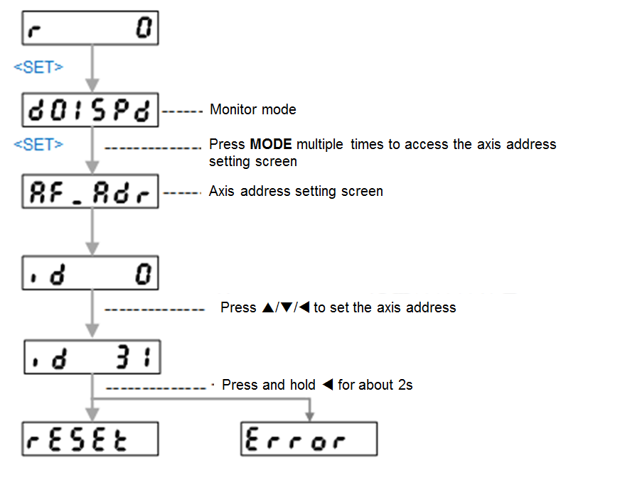
If reset is displayed, the station address is set successfully.
Power off and restart the drive to make the setting take effect.
If Error is displayed, the station address setting has failed. Restart the drive and try again.
Open NcEditor. Set the axis station address parameters to the values set by the drive front panel.