Commissioning Steps
This section introduces the procedure of follow-up commissioning.
Before commissioning, do the following:
- To get familiar with layout and application of follow-up interface, see Interface Overview for details.
- See Get Preparation for what to prepare.
To do commissioning for follow-up, do the following:
To open Follow-up Control dialog box, do one of the following:
- In drawing toolbar, click
 .
. - In menu bar, click System → Follow Control.
- In drawing toolbar, click
Do the following:
- Detect capacitance
- Optional: Calibrate servo
This step is unnecessary if the system is in velocity loop control mode. - Calibrate capacitance
After commissioning, see Check Follow-up to check whether the operation is successful.
Get Preparation
To get preparation, do the following:
Check and confirm that the hardware has been well connected.
See Install Hardware for details.
Check and confirm that parameters related to drive and follow-up have been set correctly.
See Set Drive Parameters and List of Parameters for details.
To check PG Frequency Dividing Ratio of Z, do the following:
Move Z-axis along positive or negative direction in jog mode.
Observe the corresponding step length change of Z-axis coordinate and make a distinct between the increase and decrease of the changing value.
If Z-axis coordinate change is different from the specified step length, it indicates that the parameter is wrong and you should modify it. See PG Frequency Dividing Ratio is Set Incorrectly for details.
If Z-axis coordinate change is the same with the specified step length, it indicates that the parameter is correct.
Check and confirm that there is no alarm and Current Capacitance shows in the software.
Check and confirm that Z-axis direction is adjusted correctly.
See Adjust the Axis Direction for details.
To ensure basic motion and coordinate display are correct, and Z-axis can return to the machine origin, check system parameters in the software.
Detect Capacitance
This operation is used to observe the capacitance and check its stability.
To detect capacitance, do the following:
Move the cutting head to the workpiece and check whether current capacitance changes in real time.
When the cutting head touches the workpiece, the capacitance should be zero. If it is not zero, see The Capacitance is not 0 when the Cutting Head Touches the Workpiece/The Cutting Head Keeps Moving Downward during Calibration for details.
Set parameter Z Up Position. See Parameters Setting Area for details.
To check whether the current capacitance is stable, do the following:
Move the cutting head to the position 30mm far from the workpiece surface and keep it still.
Observe whether the change of the current capacitance is within 30Hz:
If it is, it indicates that the current capacitance is stable.
If it is not and the last three numbers of the current capacitance change obviously, it indicates that the electric interference is serious.
See Electric Interference is Serious for details.
Calibrate Servo
This operation is used to eliminate the zero drift of servo motor caused by velocity loop control.
To judge zero drift, do the following:
- Turn on the servo motor and enable servo in the software.
- Observe the display interface of the servo drive. If the value changes greatly, it indicates large outside interference. Proceed to next step.
- Optional: Observe the coupling at the joint of Z-axis motor and screw. You can find that the coupling rotates slightly.
To calibrate servo, do the following:
To move the cutting head to the middle of the stroke range and avoid the cutting head exceeding the stroke, click X+/X-/Y+/Y- in manual control area.
Click
 . The system automatically generates the value of parameter Servo Compensation Parameter.
The cutting head slightly moves back and forth to compensate the error caused by zero drift.
Calibrate Capacitance
This operation is used to measure the corresponding distance between capacitance and position between the cutting head and the workpiece.
Before calibrating capacitance, do the following:
- To decide the workpiece type for calibration, set parameter Nonmetal Mark.
- Ensure the capacitance is stable.
To calibrate capacitance, do the following:
Move the cutting head to the position about 5mm far from the workpiece surface, and keep the workpiece still all the time.
Click
 . The system starts to calibrate capacitance for 20s.
During calibrating capacitance, the cutting head does the following:
- Move downward slowly to detect and touch the workpiece.
- Move upward 5mm after it touches the workpiece.
- Move downward slowly to detect and touch the workpiece again.
- Move upward the specified calibration distance after it touches the workpiece.
The system collects the calibration data and generates the calibration data:
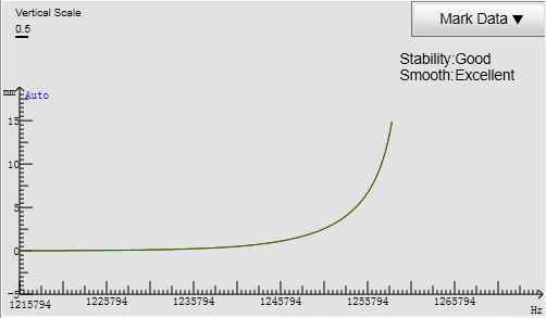
Stability
The difference of the collected data between the segment of the cutting head down 5mm before touching the workpiece and that of the cutting head up 5mm after touching the workpiece.
The larger the difference is, the smaller the stability is.
If the stability is Bad, the fluctuation may be relatively more unstable or the external interference may be relatively more serious. You need to calibrate capacitance again.
Smooth
The smoothness of the curve.
If the smoothness is Bad, the curve is not flat with ups and downs or burrs. You need to calibrate capacitance again.
Note: During calibrating capacitance, e-stop button is for use at any time in case of machine tool damage caused by cutting head continuous moving downward if the capacitance for touching the workpiece is incorrect.
Check Follow-up
This operation is used to check if follow-up commissioning succeeds.
Before checking follow-up, ensure the calibration is successful.
To check follow-up, do the following:
Turn on and off the follow-up and observe whether the cutting head shakes and whether the follow-up distance is correct.
It is suggested to move a screw driver or a tiny metal plate back and forth under the cutting head and observe whether the cutting head moves up and down along the position of the screw driver or the metal plate and whether the cutting head shakes.
To improve security, set parameter Out Margin Check as Yes.
Draw a toolpath, cut it without turning on laser, and observe whether the cutting head shakes during following.