FAQs
This section mainly answers the following common questions that you may encounter during follow-up commissioning:
- PG frequency dividing ratio is set incorrectly
- Electric interference is serious
- The capacitance is not 0 when the cutting head touches the workpiece / The cutting head keeps moving downward during calibration
- The actual follow-up height is different from the calibrated follow-up height
- The cutting head keeps moving downward during calibration
- The cutting head frequently stops working while the capacitance feedback is normal, the calibration result is well and no alarm occurs
- The cutting head shakes substantially during cutting a thin sheet, which causes the distortion of the contour of the cutting workpiece
- An alarm "follow-up process at error status" occurs when Z-axis moves in jog mode or the follow-up is turned on directly
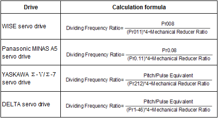
PG Frequency Dividing Ratio is Set Incorrectly
Cause
Parameter PG Frequency Dividing Ratio is set incorrectly.
Solution
Modify its value by adjusting related drive parameters according to the following calculation formula:
Electric Interference is Serious
Cause
Physical hardware
The drive, Lambda 5E terminal board and EX33A terminal board are not well grounded.
The cable shielding layer is not well treated, that is, the shielding layer is broken and the shielding nest is not wired to the outer metal frame.
The No.4 pin of M16 tow cable with 4-core air plug and follow-up amplifier are not well connected.
The follow-up amplifier and the machine tool are not connected tightly and completely.
The cable does not work well.
The machine tool is not well grounded.
Software setting
Value of parameter Sensitivity is too large.
Value of parameters In Position Tolerance and Zero Limit Speed Range are too small.
Solution
Physical hardware
Reconnect the hardware.
Fix the shielding layer and wire the shielding nest to the outer metal frame.
Connect the No.4 pin of M16 tow cable with 4-core air plug and the follow-up amplifier.
The resistance value between the two should be very small, and 0 is the best.
Connect the follow-up amplifier and the machine tool tightly and completely.
Change the cable.
Find out the cause for being not well grounded, and solve it.
Software setting
Slightly reduce the value of parameter Sensitivity.
Slightly increase the values of parameters In Position Tolerance and Zero Limit Speed Range.
Note: Please be careful. Because these operations may lead to lower precision of follow-up and cutting separately.
The Capacitance is not 0 when the Cutting Head Touches the Workpiece/The Cutting Head Keeps Moving Downward during Calibration
Cause
- The workpiece and the machine tool are not connected or not well connected.
- Insulator like rust and paint exists on the calibrating position of the workpiece.
Solution
Manually move the cutting head downward with small step size like 0.1 until it touches the workpiece, and check current capacitance.
Set the value of parameter Touch Part Capacitance greater than current capacitance.
The Actual Follow-up Height is Different from the Calibrated Follow-up Height
Cause
Enormous change of the environment temperature causes the deviation of the calibration curve.
Solution
Calibrate the distance again.
See Commissioning Steps for details.
The Cutting Head Frequently Stops Working while the Capacitance Feedback is Normal, the Calibration Result is Well and No Alarm Occurs
Cause
The external force caused by gas that flows through the cutting head leads to poor connection between the contact inside the ceramic ring and the cutting head signal port, and then an alarm of touching workpiece occurs. As a result, the cutting head stops working even though the nozzle does not touch the workpiece during cutting.
Solution
Change the ceramic ring.
The Cutting Head Shakes Substantially during Cutting a Thin Sheet
Cause
The air pressure is high.
Solution
Set parameter Sensitivity as 2 (default value: 5) and parameter In Position Tolerance as 0.2 (default value: 0.1).
An Alarm Follow-up Process at Error Status Occurs when Z-axis Moves in Jog Mode or the Follow-up is Turned on Manually
Cause
- The axis direction of the drive is incorrect and outside interference leads to zero drift.
- Outside interference leads to zero drift.
Solution
Do the following (taking a Panasonic A6 series servo drive as an example):
To judge whether the axis direction of the drive is correct and solve the problem, do the following:
Click Z+ / Z- in the software and see whether the cutting head moves:
- If it does, it indicates the direction is correct.
- If it does not, it indicates that the direction is incorrect. Proceed to next step.
Optional: Modify the value of parameter Axis Direction and restart the drive.
To adjust zero drift, do the following:
Ensure the value of parameter Pr3.15 is the default value 0.
Turn on the drive, and automatically adjust zero drift AF_oF1, AF_oF2 and AF_oF3.
Turning on the software is not required in this step.