Interface Overview
In this section, you can quickly get familiar with Follow-up Control dialog box and execute related operations.
To open Follow-up Control dialog box, do one of the following:
- In drawing tool bar, click
 .
. - In menu bar, click System → Follow Control.
You can switch between the following interfaces by clicking the buttons on the left:
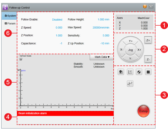
System interface
Param interface
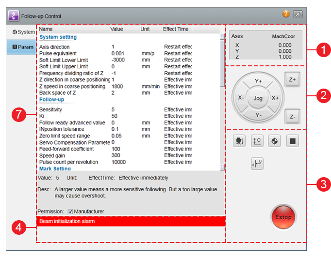
- Axis coordinate display area
- Manual control area
- Follow-up control buttons
- Alarm display bar
- Waveform display area
- Main parameters area
- Parameters setting area
Axis Coordinate Display Area
It is used to show the following:
- Workpiece coordinates
- Machine coordinates

You can switch between workpiece coordinates and machine coordinates by clicking WorkCoor/MachCoor.
Manual Control Area
It is used to move the machine tool manually.
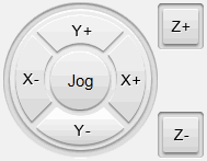
It includes the following:
Axis direction buttons
Used to move each axis towards positive or nagative direction.
Feed mode button
Used to select one of the following feed mode by clicking the circular button:
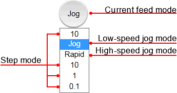
Jog mode
Including low-speed jog mode and high-speed jog mode.
If you click an axis direction button, the machine tool will move at jog/rapid jog speed until you release the button.
If you click several axis direction buttons at the same time, the clicked axes will move at the same time at jog/rapid jog speed until you release the buttons.
Step mode
If you click an axis direction button, the machine tool will move the customized step size.
You can set step size by doing one of the following:
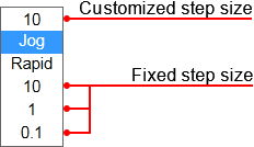
To customize step size, click the first button, and enter the value in Customize Step Size dialog box.
To set fixed step size, click one of the last three buttons.
Follow-up Control Buttons
It is used to control the machine tool to execute operations related to follow-up.
It includes the following:
 : Follow-up
After the button is clicked, the system automatically starts to follow at the presence of calibration data.
To stop following and move Z-axis to the berth point, click the button again.
To end follow-up with Z-axis stopping at the current position, click
 .
. : Capacitance Calibration
After the button is clicked, the system automatically calibrates capacitance.
To stop automcatic calibration, click the button again.
 : Z-axis Homing
After the button is click, Z-axis returns to the machine origin.
To stop returning to the machine origin, click the button again or click
.After returning to the machine origin, sign
 appears before Z-axis.
- : Stop
After the button is clicked, the system stops machining and enters idle status.
It is used to normally stop machining task during follow-up control.
 : Servo Calibration
It is exclusive for velocity loop control mode.
After the button is clicked, the system executes compensation and eliminate the zero drift of a servo motor.
 : E-stop
After the button is clicked, the system stops emergently.
Waveform Display Area
It is used to switch among the following waveform pages by clicking button  on the upper right:
Mark Data page
Used to show the corresponding relationship between capacitance and position between the cutting head and the workpiece during calibrating capacitance.
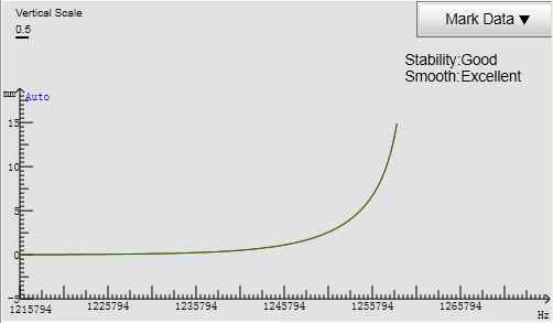
X-axis coordinate shows the capacitance while Y-axis coordinate shows the distance between the cutting head and the workpiece.
Real-time Capacitance page
Used to show real-time change of capacitance in certain time.
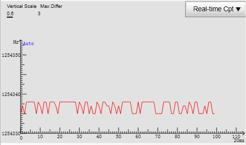
X-axis coordinate shows time while Y-axis coordinate shows the capacitance.
Max Differ on the upper left shows the difference between the maximum capacitance and the minimum one when the cutting head and the workpiece are still.
The larger the value is, the stronger the interference is and the less stable the capacitance measurement is. Thus, the ideal value is no more than 30.
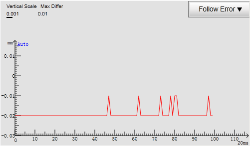
Follow Error page
Used to show the difference between current follow-up height and the set value of parameter Follow Height, so as to reflect the follow-up dynamic precision.
In this page, you can do the following:
Pause the waveform change:
If you double click within the coordinate,
 at the top of Y-axis coordinate will turn into
  .
.Set scale parameters:
If you right click within the coordinate, a scale parameter dialog box will pop up:
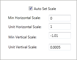
If Auto Set Scale is checked, the system will automatically set scale parameters. At this time, you cannot manually modify the parameters.
If Auto Set Scale is unchecked,
at the top of Y-axis coordinate will disappear. At this time, you need to manually modify the parameters.To confirm the setting, click your mouse or press Enter.
Main Parameters Area
It is used to show parameters for monitoring, including:
Real-time monitoring parameters (unchangeable):
Follow Enable
Used to show the status of follow-up enabling.
After
is clicked, follow-up enabling is opened and the value of this parameter turns into Enabled.Z Speed
Used to show current running speed of Z-axis.
Z Position
Used to show current machine coordinate of Z-axis.
Capacitance
Used to show current capacitance.
The smaller the distance between the cutting head and the workpiece is, the smaller the value is.
When the cutting head touches metal workpiece, the value turns into zero.
Some common used parameters (changeable):
- Follow Height
- Max Speed
- Sensitivity
- Z Up Position
See List of Parameter for details.
You can modify parameters by doing one of the following:
- Click the current value and enter a value in the dialog box.
- Move the cursor to the right of the value and click the arrow
 to modify it.
Parameters Setting Area
It is used to show all parameters related to follow-up control. See List of Parameters for details.
According to different permissions and identities, follow-up parameters can be divided into operator parameters and manufacturer parameters. The system shows operator parameters by default.
If you need to check manufacturer parameters, check Manufacturer and enter the password.
If you need to modify a parameter, double click the value and enter a value.