Set a Lead Line
This operation is used to avoid machining error or damage to the workpiece caused by long time duration of laser above the start position, so as to improve machining accuracy.
According to the leading direction, lead line can be divided into the following:
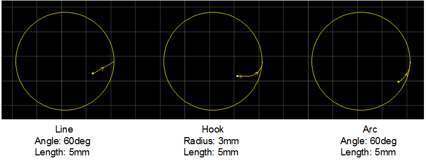
- Lead-in line: consisting of line lead line, arc lead line and hook lead line.
- Lead-out line: consisting of line lead line and arc lead line.
To set a lead line, do the following:
Select the target object.
To open Set dialog box, do one of the following:
- In tool bar, click
 .
. - In menu bar, click Object → Lead Line → Set.
- In drawing window, right click and select Lead Line → Set.
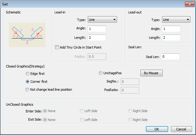
Set dialog box pops up:

- In tool bar, click
Select a lead line type.
Lead line type depends on the cutting technic.
Set related parameters of the lead line.
Set position of the lead line:
If you select a closed object, select a lead line strategy and set seal length:
- Edge first: set the lead line at the center position of the longest edge of the object.
- Corner first: set the lead line at the position with larger angle in the object.
- Not change lead line position: change the type of the previous lead line without changing its position.
- UnchangePos: enable segment number and position ratio.
- By Mouse: the cursor turns into
 . Click on the edge of the object to specify the position of the lead line.
If you select an unclosed object, select a leading method according to the machining direction:
Lead in
Left Side/Right Side: lead in on the left/right of the machining direction.
Lead out
Left Side/Right Side: lead out on the left/right of the machining direction.
Optional: To modify the lead line, do the following:
Do one of the following:
- In menu bar, click Object → Lead Line → Set Start Point.
- In drawing window, right click and select Lead Line → Start Point.
Do one of the following:
- To modify the position of the lead-in line, click on the edge of the object.
- To draw a line-type lead-in line from outside to the edge on the object, click on the outside and the edge of the object.
If you need to check the lead line, do one of the following:
- In menu bar, click Object → Lead Line → Check Lead-in/out Line.
- In drawing window, right click and select Lead Line → Check Lead-in/out Line.
The system checks and cuts the lead line automatically and properly.
Result of lead line shows as follows:
There is no circle in the lead line:

There is a circle in the lead line:

Lead Line Parameters
Angle
: For a line-type lead line, it refers to the angle between the lead line and the tangent line of the intersection.
: For an arc-type lead line, it refers to the central angle.
Radius
: For a hook-type lead line, it refers to the radius of the arc.
Length
: For a line-type/arc-type lead line, it refers to the length of the line/arc.
: For a hook-type lead line, it refers to the sum of the radius of the arc and the length of the line.
Add Tiny Circle at Start Point
: Add a tiny circle at the start point of the lead-in line, so as to solve the problem that the accumulation of slag influences cutting effect during piercing a thick plate.
Add Tiny Circle at Start Point-Radius
: Radius of the hole at the start point of the lead line.
Seal Len
: If the value is larger than 0, it means that the lead line is closed and the cutting head will cut at the sealing position.
: If the value is smaller than 0, it means that the lead line is unclosed and the cutting head won't cut through at the sealing position.
: Range: [-500, 500]mm
Seg No.
: There may exist N segments (N is a natural number) on the selected object. Each segment corresponds to a segment number. Setting a segment number is used to select the corresponding segment on which the lead line is.
: -1 refers to taking the whole object as a segment.
Pos Ratio
: The ratio of the distance between the start point of the lead line and the start point of the corresponding segment to the total length of the segment.
: Range: [0, 0.999]