Interface Overview
NcEditor V12 Laser Cutting CNC System includes the following interfaces:
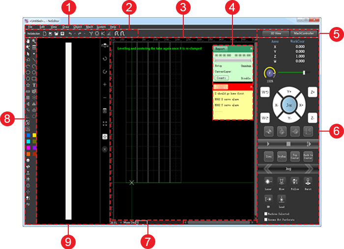
Interface of Sheet Cutting Configuration
Used to cut sheets.
It is shown as follows:
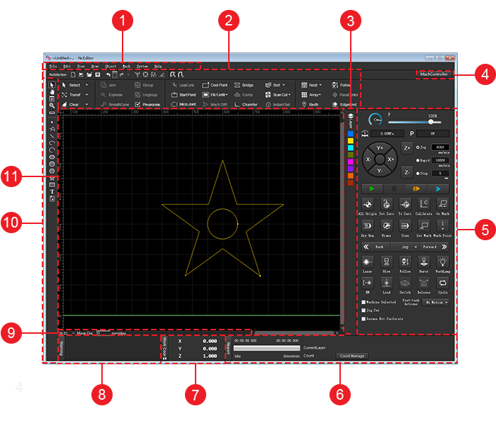
- Menu bar
- Common tool bar
- Layer tool bar
- Window display button
- Machine control area
- Running report bar
- Axis coordinate display area
- Alarm bar
- Status bar
- Drawing tool bar
- Drawing window
Common Tool Bar
It is used to show frequently used instructions.
 : New
: NewUsed to create a new file.
 : Import
Used to import a/an G/NC/DXF/DWG/PLT/ENG file.
 : Open
Used to open a NCE file.
 : Save
Used to save a toolpath file.
A new file is saved as a NCE file.
 : Undo
Used to go back a previous state.
 : Redo
Used to recover canceled operations.
 : Show order
Used to show the machining order and hide it by clicking the button again.
 : Show direction
Used to show the machining direction and hide it by clicking the button again.
 : Highlight unclosed objects
Used to mark all unclosed objects with special color or symbols.
 : Clear trace
Used to clear the machining trace.
 : Catch
Used to enable/disable catching function. See Catch Options for details.
 : Catch option
Used to catch option. See Catch Options for details.
 : Select objects
Used to select unclosed objects, tiny objects, all objects of the same layer, inner objects, outer objects, similar objects. See Select Objects for details.
 : Transform objects
Used to translate objects, rotate objects, mirror objects vertically or horizontally. See Translate Objects and Rotate Objects for details.
 : Do clearing
Used to clear some set technics.See Do Clearing for details.
 : Combine objects
Used to open Combine dialog box and combine objects. See Combine Objects for details.
 : Explode objects
Used to trim the toolpath. See Explode Objects for details.
 : Smooth polylines
Used to make polylines flat and even. See Smooth Polylines for details.
 : Group objects
Used to bind several objects. See Group Objects for details.
 : Ungroup objects
Used to separate the grouped objects. See Ungroup Objects for details.
 : Preprocess
Used to open Instant Pre-process dialog box when several target objects are selected and preprocess with one click. See Preprocess with One Click for details.
 : Set a lead line
Used to open Set dialog box and set a lead line. See Lead Line for details.
 : Set start point
Used to set the start point of the lead line. If there is no lead line, the system starts machining from the start point by default.
 : Execute micro joint
Used to open Micro Joint dialog box and set related parameters. See Micro Joint for details.
 : Add cooling points
Used to open Cooling Point dialog box and add cooling point. See Cooling Point for details.
 : Set fill or unfill
Used to set fill or unfill. See Set Fill or Unfill for details.
 : Change machining direction
Used to open Set Machining Direction dialog box and set it. See Change the Machining Direction for details.
 : Bridge objects
Used to open Bridge dialog box and bridge objects. See Bridge Objects for details.
 : Compensate kerf
Used to open Kerf Compensation dialog box and compensate the kerf. See Compensate the Kerf for details.
 : Add chamfer
Used to open Chamfer dialog box and compensate the kerf and add chamfers. See Add Chamfer.
 : Sort machining order
Used to set the machining order. See Manually Change the Machining Order for details.
 : Set scan cutting
Used to replan the toolpath to find the most efficient path for machining by turning laser on/off, so as to avoid unnecessary tool lifting and feeding and improve machining efficiency. See Set Scan Cutting for details.
 : Execute instant setting
Used to set fill/unfill, lead line, machining direction, machining order and kerf compensation with one click. See Execute instant setting for details.
 : Nest objects
Use to select a nesting method. See Nest Objects for details.
 : Execute array
Use to select rectangular array, circle array and circle fill. See Execute Array for details.
 : Set berth point
Use to set the berth point as the workpiece origin. See Set the Workpiece Origin for details.
 : Set follow-up
Used to open Follow-up Control dialog box. See Follow-up for details.
 : Control focus
Used to open Focus Control dialog box. SeeControl Focus for details.
 : Find edges
Used to open Edge Finding dialog box. See Find Edges and Locate Position for details.
Layer Tool Bar
It is used to specify a layer and open Layer Setting dialog box so as to set general parameters and technics for the layer.
See Layer Function for details.
Window Display Button
It is used to show/hide the machine control area.
See Machine Control Area for details.
It is shown as follows:

Machine Control Area
It includes the following:
- Feed override control bar
- Pressure and Power check bar
- Manual control area
- Common operation buttons
- Machining control area
- Machining selection area
Feed Override Control Bar
It is used to control current feed speed by adjusting current feed override.
It is shown as follows:

The relationship among current feed speed, current feed override and set feed speed is as follows:
Current feed speed = Current feed override * Set feed speed
To adjust feed override, do one of the following:
- Drag the slider.
- Repeatedly click on the target position on the slider.
- Click the slider and press ↑/↓ or PgUp/PgDown on the keyboard.
Pressure and Power Check Bar
It is used to check the cutting pressure and power of the laser.
It is shown as follows:

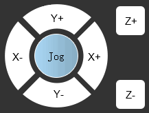
Manual Control Area
It is used to manually move the machine tool.
It is shown as follows:

Axis direction buttons
Used to move each axis towards positive or negative direction.
Note: Please do not click an axis direction button too frequently because the system needs a certain time to execute the command.
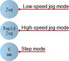
Feed mode button
Used to select among the following feed modes:
To switch to low-speed jog mode, click Jog. The machine tool moves at the jog speed when you click an axis direction button or several axis direction buttons and stops when you release it or them.
You can change the jog speed in the input box. The default jog speed is 6000mm/min.
To switch to rapid-speed jog mode, click Rapid. The machine tool moves at the jog speed when you click an axis direction button or several axis direction buttons and stops when you release it or them.
You can change the jog speed in the input box. The default jog speed is 18000mm/min.
To switch to step mode, click Step. The machine tool moves the step size when you click an axis direction button.
You can change the step size in the input box. The default customized step size is 5mm.
Note: The step size should not be too large to avoid damage due to misoperation.
Common Operation Buttons
It is used to execute the following common operations:
 : All to origin
Used to return all axes to the machine origin.
 : Set workpiece origin
Used to set the workpiece origin.
 : Workpiece origin
Used to control the cutting head to return to the workpiece origin.
 : Calibrate
Used to set a follow-up height.
 : Return mark
Used to return the position of the selected mark point. You should select the target mark point by clicking the button Mark Point in the machine control area.
Machining Control Area
It includes the following:
 : Start
Used to start machining from the beginning.
 : Stop
Used to stop machining.
 : Breakpoint position
Used to locate the exact interrupted position when the power interruption or e-stop occurs and the workpiece origin is secured.
When you need resume machining from the exact interrupted position but cannot determine the security, you should click the button. And before clicking the button Breakpoint resume, ensure the cutting head is on the right position.
 : Breakpoint resume
Used to resume machining from the exact interrupted position when the power interruption or e-stop occurs and the workpiece origin is secured.
Related parameter: Retract for Breakpoint Resume.
 : Dry run
Used to run the machine tool without turning on related ports about laser and machining. There is no actual machining.
 : Cut frame
Used to confirm the machining range by running the system along the frame of the toolpath.
 : Simulation
Used to execute simulation to check the toolpath in real-time.
 : Mark coor
Used to mark the coordinate of the current point.
 : Mark point
Used to set the current points as the mark point 1 ~ mark point8.
 : Jog
: JogUsed to switch between the jog mode and step mode by clicking
 .
.In Jog mode, press
 /
/  and the machine tool does not stop moving until you release it.
In Step mode, press
/ and the machine tool only moves according to the set step size.- : Go forward
Used to control the machine tool to move forward along the toolpath.
- : Go backward
Used to control the machine tool to move backward along the toolpath.
 : Laser
Used to turn on/off the laser valve by pressing/releasing the button.
It is turned on automatically when machining starts.
 : Blow
Used to turn on the blow valve by clicking the button and turn it off by clicking the button again.
It is turned on automatically when machining starts and is turned off after the set time.
 : Follow-up
Used to turn on follow-up valve by clicking the button to keep the distance between the nozzle and the workpiece surface and turn it off by clicking the button again.
It is turned on automatically when machining starts.
 : Burst
Used to turn on the laser valve for a certain time.
It keeps on for the set burst time until it is turned off automatically.
 : Shutter
Used to manually turn on the laser shutter.
To eject laser light, first, turn on the laser shutter; then, open the laser valve.
 : Work light
Used to turn on the work light by clicking the button and turn it off by clicking the button again.
 : Lead light
Used to manually turn on the red light, which is a kind of guide light.
It is used to point out the position of laser on the sheet.
 : Exchange workbenches
Used to exchange workbenches, so as to improve the machining efficiency.
 : Release
Used to manually control the machine tool to release workbenches during exchanging workbenches.
 : Cycle machining
Used to open Cyclical Machining dialog box and set cycle machining. See Set Cycle Machining for details.
Machining Selection Area
It includes the following:
Machine Selected
Used to execute machining, including machining, dry run, simulation, cutting frame, machining from the near point and breakpoint resume for the selected objects.
Jog Cut
Used to manually control the machine tool with laser on. Check it and then manually move the axis for a certain distance.
When jog cutting ends, it is unchecked by default. The laser will not be automatically turned on during the next machining.
Resume Not Pierce
Used to execute breakpoint resume without piercing during cutting a thick sheet, so as to avoid damage to the sheet and effect on machining.
Actions after Machining
Used to select the actions after the machining ends including no motion, returning to the fixed point, returning to the workpiece origin and returning to the mark point.
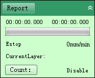
Running Report Bar
It is used to show running status of the machine tool.
It is shown as follows:

You can do the following:
Check the following:
- Current machining time
- Remaining machining time
- Current system status
- Current machining speed
- Current machining layer
Click Count Manage and enable counting machining function. See counting machining function for details.
Clicking Report and check the statistics. See Statistics for details.
Axis Coordinate Display Area
It is used to show the following:
- Workpiece coordinates
- Machine coordinates
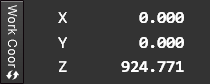
To switch between workpiece coordinates and machine coordinates, click WorkCoor/MachCoor.
After returning to the machine origin, sign  appears before each axis.
Alarm Bar
It is shown as follows:
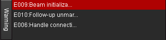
It is used to check alarm information.
You can do the following:
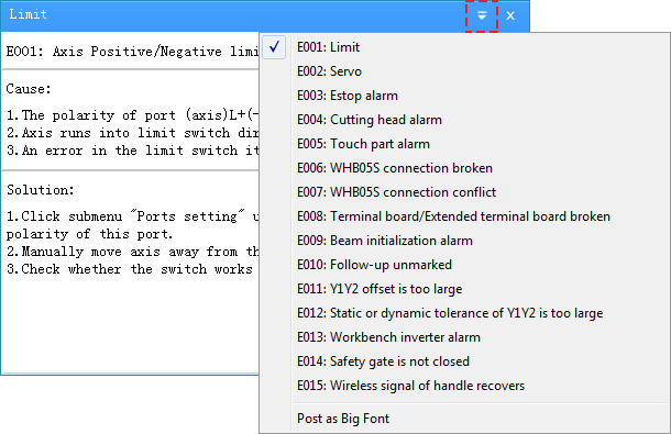
To check causes and solutions of alarms, click Warning.
To check the alarm type, click
 .
.
Status Bar
It is used to show the following:
Related information of current drawing objects: drawing steps and meaning, step result, tuning distance, etc.
Tips during machining.
Drawing Tool Bar
It is used to draw all kinds of objects with drawing tools. See Drawing Operations for details.
Drawing Window
It is used to draw and preview objects.
Interface of Tube Cutting Configuration
Used to cut tubes.
It is shown as follows:
- Menu bar
- Common tool bar
- Drawing window
- Running information bar
- Window display buttons
- Machine control area
- Status bar
- Drawing tool bar
- 3D view area
Common Tool Bar
It is used to show frequently used instructions.
It differs in the number of selected objects:
If no object is selected, it shows the following:
- : New
Used to create a new file.
- : Import
Used to import a/an G/NC/DXF/DWG/PLT/ENG file.
- : Open
Used to open a NCE file.
- : Save
Used to save a toolpath file.
A new file is saved as a NCE file.
- : Undo
Used to go back a previous state.
- : Redo
Used to recover canceled operations.
- : Show order
Used to show the machining order and hide it by clicking the button again.
- : Show direction
Used to show the machining direction and hide it by clicking the button again.
- : Highlight unclosed objects
Used to mark all unclosed objects with special color or symbols.
- : Clear trace
Used to clear the machining trace.
- : Catch
Used to enable/disable catching function. See Catch Options for details.
- : Catch option
Used to open Catch Option dialog box and select feature points. See Catch Options for details.
If one or more objects are selected, it shows related information of the objects and the following buttons:
 : Preprocess
See Preprocess with One Click for details.
 : Group
See Group or Ungroup Objects for details.
 : Ungroup
See Group or Ungroup Objects for details.
Drawing Window
It is used to draw and preview objects.
In tube cutting configuration, the development effect of a rectangular tube shows in drawing window for ease of drawing:
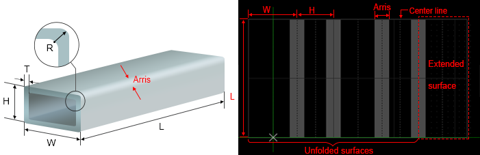
Length of an arris: depending on the corner radius and thickness of the rectangular tube.
Extended face: corresponding to the first face of the actual tube.
Center line: including face center line and arris center line. It exists on each face. When you drag the object, the center of the object automatically gets close to the center line.
Running Information Bar
It is used to show running status and alarms of the machine tool.
It includes the following:
Report Bar
It is shown as follows:
You can do the following:
Check the following:
- Current machining time
- Remaining machining time
- Current system status
- Current machining speed
- Current machining layer
Click Count Manage and enable counting machining function. See counting machining function for details.
Clicking Report and check the statistics. See Statistics for details.
Alarm Bar
It is shown as follows:

It is used to check alarm information.
You can do the following:
To check causes and solutions of alarms, click Warning.
To check alarm type, click
.
Window Display Buttons
: show/hide machine control area
See Machine Control Area for details.
Machine Control Area
It includes the following:
- Axis coordinate display area
- Feed override control bar
- Manual control area
- Common operation buttons
- Machining control area
- Machining selection area
Axis Coordinate Display Area
It includes the following:
- Workpiece coordinates
- Machine coordinates

To switch between workpiece coordinates and machine coordinates, do one of the following:
- Click
 .
. - Double click WorkCoor/MachCoor.
After returning to the machine origin, sign appears before each axis.
Feed Override Control Bar
It is used to control current feed speed by adjusting current feed override.
It is shown as follows:

The relationship among current feed speed, current feed override and set feed speed is as follows:
Current feed speed = Current feed override * Set feed speed
To adjust feed override, do one of the following:
- Drag the slider.
- Click on the target position on the slider repeatedly.
- Click the slider and press ↑/↓ or PgUp/PgDown on the keyboard.
Manual Control Area
It is used to move the machine tool manually.
It includes the following:
Axis direction buttons
Used to move each axis towards positive or negative direction.
Feed mode button
Used to switch among the following feed modes by clicking the circular button in the middle:
Jog mode
Including low-speed jog mode and high-speed jog mode.
Click an axis direction button. The machine tool moves at jog/rapid jog speed until you release the button.
Click several axis direction buttons at the same time. The clicked axes move at the same time at jog/rapid jog speed.
Step mode
Click an axis direction button. The machine tool moves the customized step size.
The default customized step size is 5mm. To customize the step size, double click the feed mode button. The value should not be too large to avoid damage due to misoperation.
Note: Please do not click an axis direction button too frequently because the system needs a certain time to execute the command.
Common Operation Buttons
It is used to execute the following common operations:
- : All to origin
Used to return all axes to the machine origin.
- : Set workpiece origin
Used to set the workpiece origin.
- : Workpiece origin
Used to control the cutting head to return to the workpiece origin.
- : Calibrate
Used to set a follow-up height.
Machining Control Area
It includes the following:
 : Start
Used to start machining from the beginning.
 : Stop
Used to stop machining.
 : Breakpoint resume
Used to resume machining from the exact interrupted position when the power interruption or e-stop occurs and the workpiece origin is secured.
- : Simulation
Used to execute simulation to check the toolpath in real-time.
- : Dry run
Used to run the machine tool without turning on related ports of laser and machining. There is no actual machining.
- : Cut frame
Used to confirm the machining range by running the system along the frame of the toolpath file.
 : Leveling and centering
Used to adjust a tube to horizontal status and find the center line of certain face of the tube.
 : Return to center
Used to move each axis to return to the center position of the tube. W-axis turns to horizontal status and X-axis returns to the center line of the tube.
 : Jog
: JogUsed to switch between jog mode and step mode by clicking
.In Jog mode, press
/ and the machine tool does not stop moving until you release it.In Step mode, press
/ and the machine tool only moves according to the set step size. : Go forward
Used to control the machine tool to move forward along the toolpath.
 : Go backward
Used to control the machine tool to move backward along the toolpath.
- : Laser
Used to turn on/off the laser valve by pressing/releasing the button.
It is automatically turned on when machining starts.
- : Blow
Used to turn on the blow valve by clicking the button and turn it off by clicking the button again.
It is turned on automatically when machining starts and is turned off after the set time.
- : Follow-up
Used to turn on follow-up valve by clicking the button to keep the distance between the nozzle and the workpiece surface and turn it off by clicking the button again.
It is turned on automatically when machining starts.
- : Burst
Used to turn on the laser valve for a certain time.
It keeps on for the set burst time until it is turned off automatically.
- : Shutter
Used to turn on laser shutter manually.
To eject laser light, first, turn on the laser shutter; then, open the laser valve.
- : Lead light
Used to manually turn on the red light , which is a kind of guide light.
It is used to point out the position of laser on the sheet.
Machining Selection Area
It includes the following:
- Machine Selected
Used to machine the selected objects, including machining, dry run, simulation, cutting frame, machining from the near point and breakpoint resume.
Resume without Piercing
Used to execute breakpoint resume without piercing during cutting a thick sheet, so as to avoid damage to the sheet and effect on machining.
Status Bar
It is used to show the following:
Related information of current drawing objects: drawing steps and meaning, step result, tuning distance, etc.
Tips during machining.
Drawing Tool bar
It is used to do the following:
- Draw objects
- Execute auxiliary editing operations
- Execute basic editing operations
- Set technics
- Set layers
3D View Area
It includes the following:
View Area
It is used to check the tube from different perspectives and preview cutting effect.
In this area, you can do the following:
Press the left button:
- To rotate the tube, drag the mouse left and right.
- To move the tube, drag the mouse up and down.
To zoom in/out the tube, scroll the mouse wheel.
View Toolbar
It includes the following:
 : Switch view
Used to observe a tube from different perspectives.
 : Rotate CW
Used to rotate the view in a clockwise direction.
 : Rotate CCW
Used to rotate the tube view in a counterclockwise direction.
 : Zoom in
Used to make the view appear larger.
 : Zoom out
Used to make the view appear smaller.
 : Best view
Used to adjust 3D view area to the best size, so as to check the toolpath effect.
 : Maximize
Used to maximize 3D view area and hide drawing window.
 : Restore view
Used to restore the maximized view to its previous size.
 : Hollow out
Used to show hollow-out-effect of objects, so as to check the cutting effect.
 : Solid
Opposite to
instruction. : Instant Hollowing
Used to show hollow-out-effect of objects which have been executed machining or dry run, while executing
instruction for other objects. : Close
Used to close 3D view area.