Product Introduction
Function Overview
Weihong's NcStudio-V15 Laser Tube Cutting Control System includes laser cutting technic processing, common layout function and laser machining control. The main functions include tool path file edit, system parameter set, customized machining process, system maintenance set and cutting control.
The tube type supports circular tube, rectangular tube, oval tube, waist tube, angle steel, channel steel and other special shaped tubes.
Introduce the Main Interface of the Software
This chapter mainly introduces the main interface of NcStudio-V15.
The graphic is as follows:
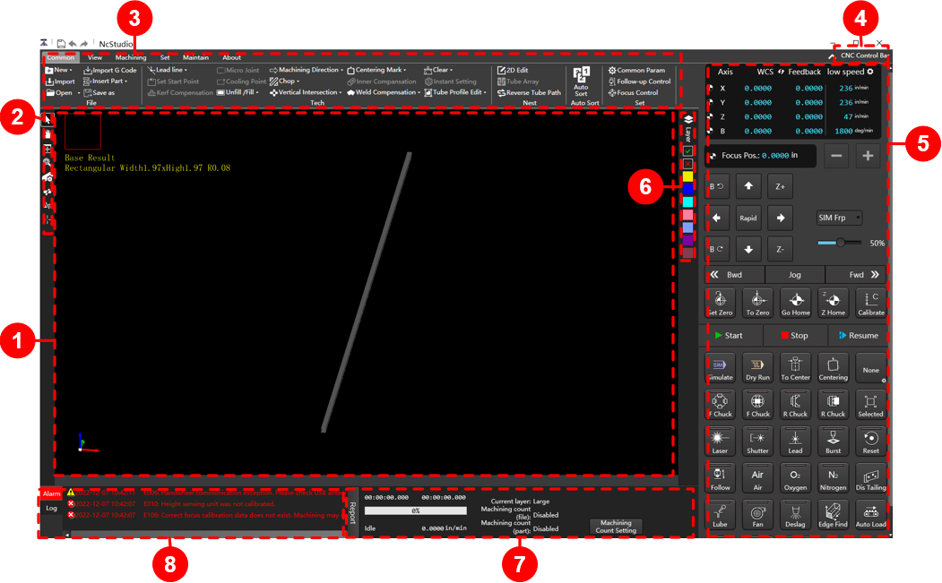
1.Drawing Area 2.Common Toolbar 3.Menu Bar 4.Machine Control Bar Display Button 5.Machine Control Bar 6.Layer Toolbar 7. Machining Information Statistics Bar 8. Alarm/Log Information Bar
Drawing Area
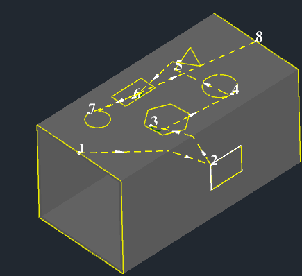
View tubes from different perspectives, preview cutting effects, and select graphics and parts to add technics.
Include the following areas:
Top left corner area: Display the tube projection section outer contour, view name, tube type and size.
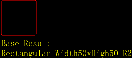
Bottom left corner area: Display the 3D coordinate system.

Middle area: Display the base layer or nest result and the added technic.
Common Toolbar
Provide common tool buttons:
| Button | Description |
|---|---|
 Select graph Select graph |
Choose any graphic you want. |
 Pan Pan |
Move the graphic in a straight line direction to change the coordinate position of the graphic without changing the shape and size of the graphic. |
 Best view Best view |
The adaptive size of the graphic is displayed in the window. |
 Zoom by Rect Zoom by Rect |
Enlarge the part of the graphic to the size of the view window. |
 Tube cutting setting Tube cutting setting |
Check the tube thickness and total tube length, which can be set. |
 Tube intersection Tube intersection |
The tube surface perforation can be made by intersecting branch tubes on the pipe, and the array can be set. |
 Tube cutting Tube cutting |
Cutting graphic is generated on the pipe to cut off the tube parts. |
 Mark point Mark point |
It is used to set the mechanical coordinate of the target position as the mechanical coordinate of the marked point, and move the cutting head back to the marked point when necessary. |
Menu Bar
The following function tabs are included:
| Tab | Function description |
|---|---|
| Common | It includes file operation, set technic, nest operation, automatic sorting and set common parameters of the machine tool. For related operations, see Load or Draw Tool Path, Edit Tool Path File, Set Common Parameters, Follow up Control, and Focus Control. |
| View | Select graphics, display technics, and adjust views. For related operations, see View Operation. |
| Machining | Machining related settings, including zeroing, centering, technic library management, machining mode selection, viewing production reports, operation reports, and logs. For related operations, see Machining Related Operations. |
| Set | It is mainly used to set system parameters, ports, drivers and lasers. Lead screw error, feed cutting compensation and special material pulling parameter setting. For related operations, see Parameter Setting. |
| Maintain | It include automatic settings, external equipment maintenance management and common maintenance management tools.br>For related operations, see System Maintenance. |
| About | It includes software language, unit, theme, password and other settings, common shortcut key description, parameter backup, installation package production, etc. For related operations, see System Management. |
Machine Control Bar Display Button
Show or hide the Machine Control Bar.
Machine Control Bar
The machine control bar includes:
Coordinate Display Area
Display WCS, MCS, feedback coordinates, low speed, rapid and step distance of each axis:
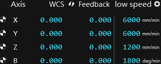
After returning to the mechanical origin, sign will appear in front of each axis.
In this area, the following operations can be performed:
Click
 to switch WCS and MCS.
Click
 to set the low speed, rapid and step of X, Y, Z and B axes.
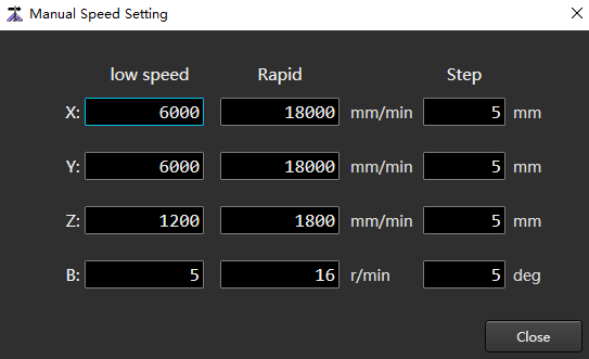
Manual Control Area
The manual control area is as follows:

Focus position
Click
 /
/  button to adjust the focus position.
Axis direction button
- Click the direction button
 (Y+)、
(Y+)、 (Y-)、
(Y-)、 (X+)、
(X+)、 (X-) 、
 、
、 to control the positive or negative movement of each axis of the machine tool.
 - Click the direction button
 、
、 to control the rotation direction of axis B.
- Click the direction button
Feed override
Before or during machining, select the following methods to adjust the feed speed.
- Drag the override speed bar with the mouse to adjust the feed speed.
- Click the target position of the override speed bar.
- After clicking the override speed bar, press the PgUp, PgDown or ↑, ↓, ←, → keys on the keyboard.
Machine tool motion control button
Click
 /
/  button,the machine tool will continuously move in reverse/forward direction along the tool path path.
- In Jog mode, release the button to stop the machine.
- In Step mode, the movement stop after setting the step size value.
Mode selection button
According to the actual situation, click
 /
/  to switch mode.
Mode Description Jog mode (default mode) ▪ Click the single axis direction button, the axis move at a continuous low speed, and stop after the button is released.
▪ At the same time, click multiple axis direction buttons. The selected axis move at a continuous low speed at the same time and stop at the same time after the button is released.
▪ At the same time, click the rapid button and the single axis direction button. The axis moves in a continuous rapid mode and stop when the button is released.
▪ At the same time, click the rapid button and multiple axis direction buttons. The axis moves in a continuous rapid mode and stop at the same time after the button is released.Step mode Click the axis direction button, and the machine tool will stop after moving the set step size (default value is 5mm).
To customize the step value, click in the upper right area of Coordinate Display Area .
Note: Do not set the step size too large or click the axis direction button frequently to avoid damage to the machine tool due to incorrect operation or too frequent operation.
Common Function Buttons
Common function buttons:
| Button | Description |
|---|---|
 |
Return to the workpiece origin. |
 |
Control the feeding axis, laser head horizontal moving axis, laser head follow up axis, rotation axis or focus axis to return to the workpiece origin. |
 |
Execute all axes back to mechanical origin. |
 |
Execute Z-axis return to mechanical origin. |
 |
Execute the specified action of cutting head. |
Machine Tool Control Button
Start and stop machining and related operations of laser cutting:
| Button | Description |
|---|---|
 |
Start this machining task from the beginning. |
 |
Stop this machining task. |
 |
After the machining is stopped, the machining shall be continued from the position where the last machining was stopped under the condition of ensuring the accuracy of the mechanical coordinates. |
 |
Enter simulate mode. The system does not drive the machine tool to perform corresponding mechanical and electrical actions, but only simulates the machining path at high speed in the drawing area. |
 |
Enter dry run mode. Run the machine tool without turn on the laser and machining related ports , check whether the machining action is correct. |
 |
Control the rotation axis of the machine tool and the transverse movement axis of the cutting head to return to the fixed position: the rotation axis return to the workpiece origin, and the transverse movement axis of the cutting head returns to the tube centerline. |
 |
Adjust the tube to horizontal and find the center of the tube. The centering method can be selected. Please refer to the buttons below for details. |
 |
Set the centering method. The text on the button indicate the currently selected centering method. You can only select the part of the centering method through this button, and the optional centering method is the centering action available for automatic matching of the current tube type. For more centering methods, see Auto Centering. |
 |
The jaws that control the front chuck release. After the chuck control type is selected in the system parameters, the chuck will be controlled by IO/torque/position through the port. |
 |
The jaws that control the front chuck clamp. After the chuck control type is selected in the system parameters, the chuck will be controlled by IO/torque/position through the port. |
 |
The jaws that control the rear chuck release. |
 |
The jaws that control the rear chuck clamp. |
 |
Select graphics during machining, including Machining, Dry Run, Simulate and Resume. |
 |
Press and hold the laser valve until it is released and closed. When machining start, the system automatically open the laser valve. |
 |
Click open shutter, and then click close. The shutter must be manually clicked to open. First open the shutter, then open the laser valve, and finally the laser will come out. |
 |
Click open lead, and then click close, it must be opened manually. The lead is used to indicate the position of the laser on the sheet. |
 |
Open the laser valve regularly. The system open the laser valve at the same time, and automatically close after continuously setting the burst parameters. |
 |
Reserved user-defined button. |
 |
Click to open the follow up valve. After opening, the distance between the nozzle and the workpiece surface can be adjusted in real time to keep it at a fixed value. At the beginning of machining, the system automatically open the follow up valve. |
 |
Click to manually open the blowing valve, and then click to close it, the blowing gas is air. At the beginning of machining, the button will be highlighted, and the system will automatically open the blowing valve to blow air. |
 |
Click to manually open the blowing valve, and then click to close it, the blowing gas is oxygen. At the beginning of machining, the button will be highlighted, and the system will automatically open the blowing valve to blow oxygen. |
 |
Click to manually open the blowing valve, and then click to close it, the blowing gas is nitrogen. At the beginning of machining, the button will be highlighted, and the system will automatically open the blowing valve to blow nitrogen. |
 |
Start dis tailing . When processing the tailings, it is necessary to ensure that the system is in an idle state, and that the feeding axis, the horizontal moving axis of the laser head, the following axis of the laser head, the clamping axis of the blanking shelf, and the axis that makes the blanking shelf move forward or backward have all returned to the original point. |
 |
Turn on lube. |
 |
Click to manually open the fan power supply, and then click to close. Set the system parameters of External Equipment Control-Exhaust category to control the fan to start or stop automatically when machining start or end. |
 |
Set the system parameter Enable Back Blow or Enable Side Blow to Yes, and click this button to enable slag removal. |
 |
Click this button, and the cutting head will perform a tube edge find. |
 |
Click this button to automatically load. |
 |
Turn on the lighting. |
 |
Enable or shield auxiliary support tube. |
Layer Toolbar
Perform layer related operations.
Including the following parts:
 :Set layer parameters.
 :Sets the selected graphic machining.
 :Set the selected graphic not machining. At this time, the graphic is white.
 :Set the color of the selected object to the color of the corresponding layer.
Machining Information Statistics Bar
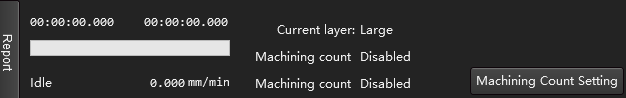
The following operations can be performed:
- Click Report to pop up the Report dialog box,View Report.
- Click Machining Count Setting to pop up the Work Count dialog box to view and set the machining count.
- View the current total machining time, the remaining time of re machining (when cycle machining is enabled), the current layer, machining count, speed, system status and other information.
Alarm/Log Information Bar
Display machining information and operation error prompt information.
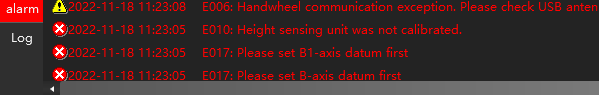
The following operations can be performed:
- Double click Alarm / Log, and the Log dialog box pop up. View Log information.
- Double click the corresponding alarm item or log information item to view the time, reason, solution or log details of the alarm in the pop up dialog box.