Loading or Drawing Tool Paths
Overview
Before machining, the tool path needs to be loaded or drawn.
After loading or drawing a graphic, you can perform the Edit Tool Path File operation.
After operating the graph, you can select the following saving operation in the menu bar to save it as a tool path file in the format of .ncexa:
Save the tool path file, click
 .
.To save the new tool path file, click
 .
.
Loading Tool Path
Drag the tool path file or nesting result file to be loaded to the software drawing area for loading, or use the following buttons to load:
Note: If the nesting result file (ncexa format) is opened, the nesting result list will be expanded and the nesting results will be added to the nesting list. Open other files without nesting results, they will be added to the base layer of the nesting list, and the nesting results list will not be automatically expanded.
| Button | Description |
|---|---|
 |
New tool path file, support: ▪ Tubes ▪ 3D Wrapping ▪ Standard Part ▪ Import 3D Part |
 |
Import tool path files in the format of .igs、.iges、.step、.stp. |
 |
Open the tool path file in the format of .ncex、.ncexa. |
 |
Import the G code format tool path file in the format of .nc、.g. |
 |
Insert a part on the spare tube in the tool path file without covering the tool path. support: ▪ Insert File ▪ 3D Wrapping ▪ Standard Part |
 |
Save tool file as .ncexa format file. |
Draw Part
Select the following methods to draw the part:
Draw graphic manually. For details, see Draw Graphic.
Generate tool path graphic through tube intersection function. For details, see Tube Intersection.
Generate tool path graphic through tube cutting function. For details, see Tube Cutting.
New Tube
Create a new standard tube.
Operating Steps:
In the menu bar, click Common →
→ Tubes to open the Tube Wizard dialog box: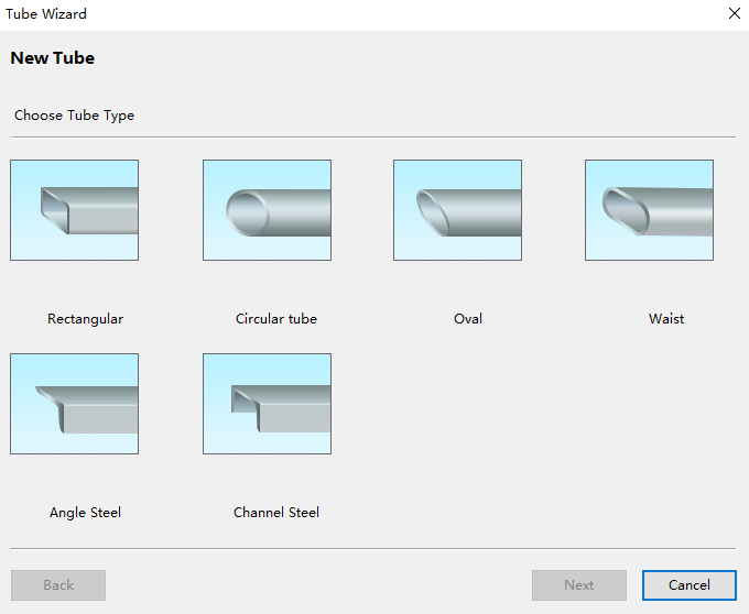
Click the corresponding tube type to open the Set Section Param dialog box:
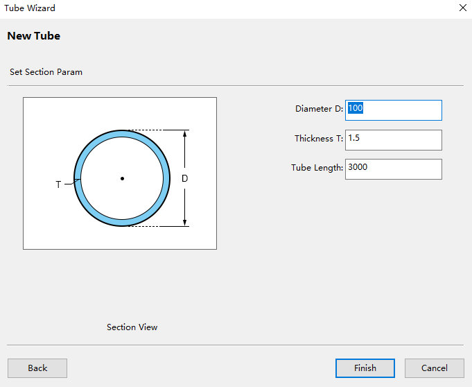
Set the section parameters. The left diagram shows the meaning of the parameters.
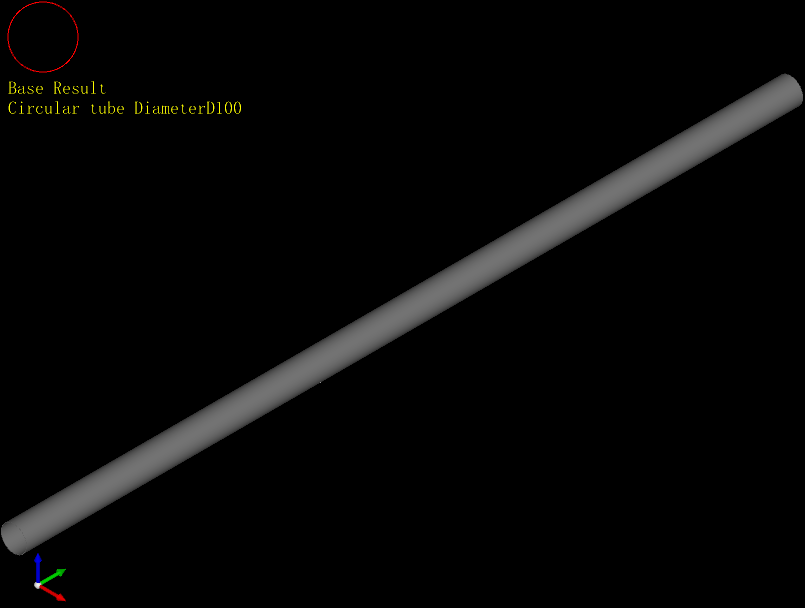
Click Finish to display the new tube in the drawing area.
3D Wrapping
The software support calling six standard tube types and configuring wrapping graphics. The wrapping graphics file support the following formats: .g、.nc、.dxf、.dwg、.plt.
Operating Steps:
In the menu bar, click Common →
→ 3D Wrapping to open the Tube Wizard dialog box:Click the corresponding tube type to open the Set Section Param dialog box:
Set the section parameters. The left diagram shows the meaning of the parameters.
Click Finish to open the file selection dialog box.
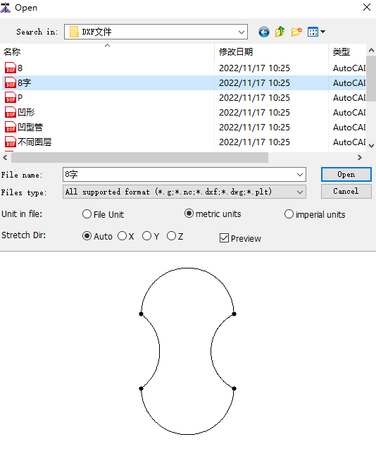
Select the wrap file.
Set unit in file.
Sets the stretch direction.
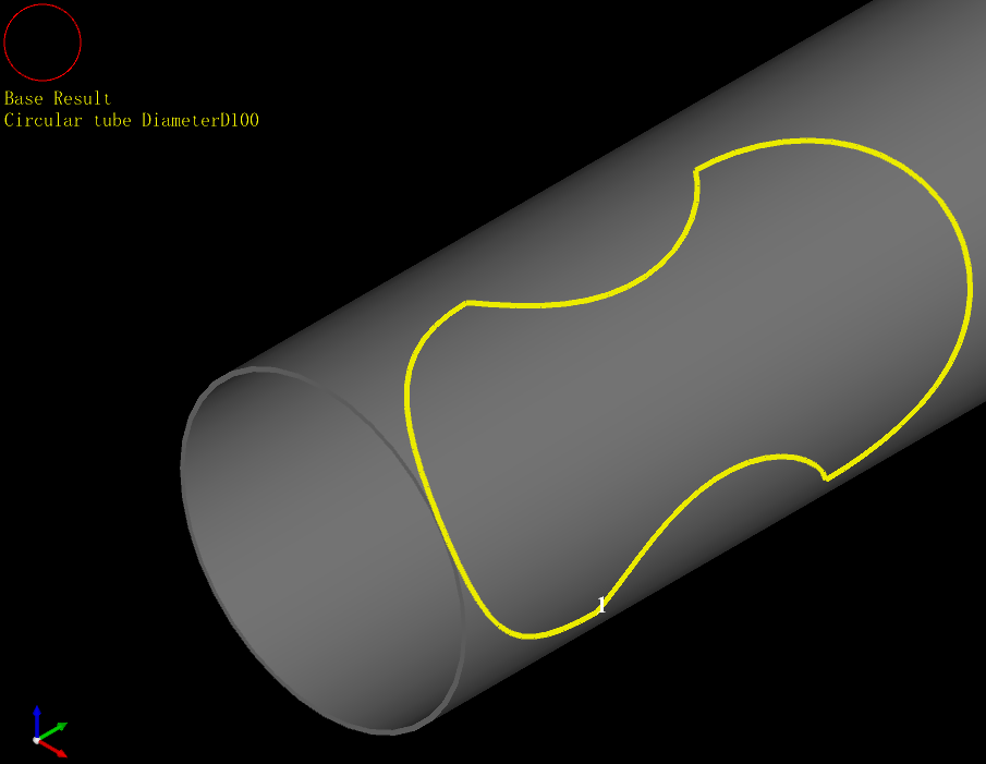
Click Open, and the drawing area will display the new 3D wrapping tube.
Standard Part
The software come with 6 commonly used standard tube type parts, which can be created by wizard to support users to use and modify part parameters.
Operating Steps:
In the menu bar, click Common →
→ Standard Part to open the Tube Wizard dialog box:Click the corresponding tube type to open the Set Section Param dialog box:
Set the section parameters. The left diagram shows the meaning of the parameters.
Click Next to open the Set Part Param dialog box:
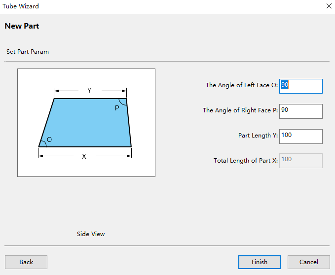
Set the section parameters. The left diagram shows the meaning of the parameters.
Click Finish to display the new tube in the drawing area.

Import 3D Part
Import 3D parts are drawn by setting tube type, section and stretch information, intersecting and cutting tubes after creating new tubes.
When creating a new tube type, specify the tube type and parameters. The tube type supports circular tube, rectangular tube, oval tube, waist tube, channel steel, and angle steel.
After using import 3D part function to draw parts, if you need to add other graphics, use 2D edit function to draw.
Operating Steps:
In the menu bar, click Common →
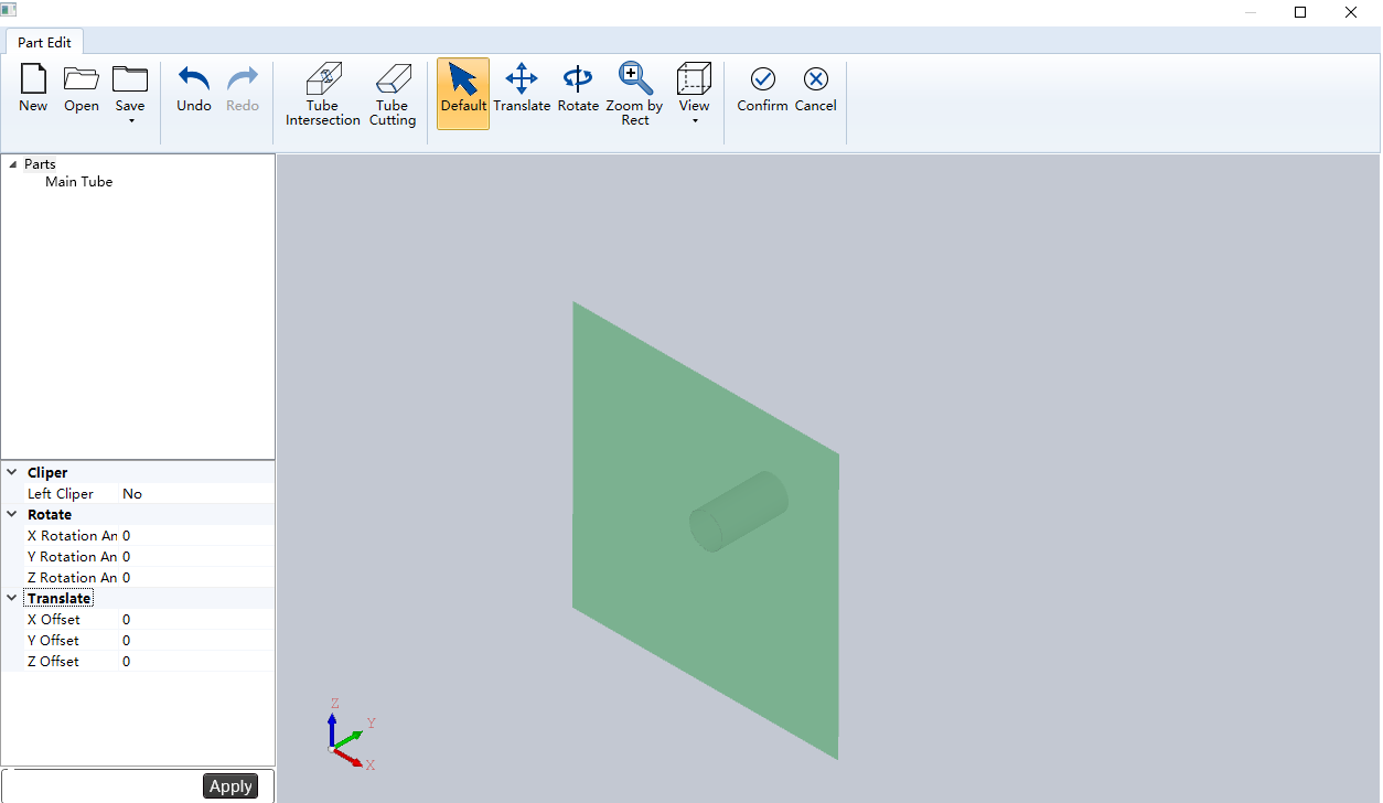
→ Import 3D Part to open the Part Edit page: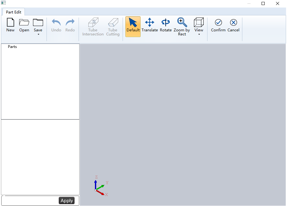
Click
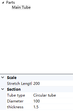
 New.The tube diagram pops up in the view, Scale and Section parameters pop up in the left list bar, as shown in the graphic:
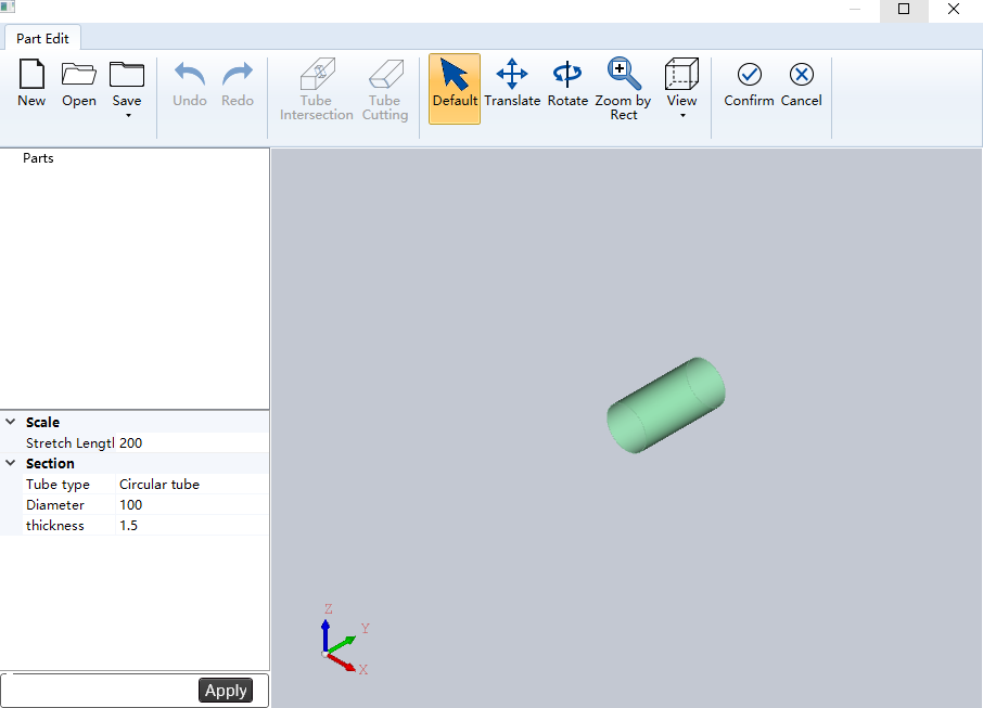
In the Scale and Section areas, select the tube type and set the tube size according to the actual needs.
After setting, click Apply, and Main Tube will be added to the Parts area.
Use the tube intersection and cutting functions to draw as needed. For details, see Set Tube Intersection and Set Tube Cutting.
After drawing, click
 Confirm in the menu bar to return to the main interface, where the new part is displayed.
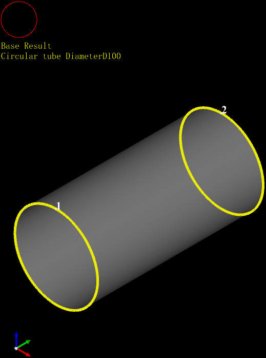
Set Tube Intersection
The intersecting function is to generate tube surface perforation through intersecting branch tube on the tube, and the array can be set. The types of intersecting holes include circular hole, rectangular hole and waist hole.
Operating Steps:
On the 3D drawing Part Edit page, click Tube Intersection in the menu bar, and the intersection parameter pops up at the lower left corner, as shown in the following graphic:
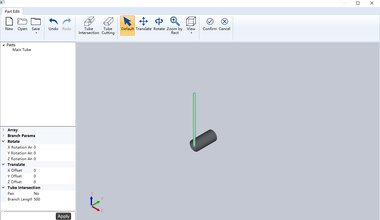
Set the parameters of translate, tube intersection, rotate, array and branch param. See the following table for detailed parameters:
Parameter Description X offset The distance between the intersecting hole center and the starting point of the main tube in the X axis direction. Y offset The distance between the intersecting hole center and the starting point of the main tube in the Y axis direction. Z offset The distance between the intersecting hole center and the starting point of the main tube in the Z axis direction. Pair The branch tube through the whole tube and generate a pair on the main tube. Yes: generated; No; Do not generate. Branch length The length of the branch tube. X rotation angle The included angle between the straight line projected by the intersecting branch tube on the YZ plane and the positive direction of the Z axis. Y rotation angle The included angle between the straight line projected by the intersecting branch tube on the XZ plane and the positive direction of the Z axis. Z rotation angle The included angle between the straight line projected by the intersecting branch tube on the XY plane and the positive direction of the Y axis. Array machining Use intersecting arrays. Yes: enabled; No: not enabled. Y array number Number of array branches in Y direction. Y array dis. Array branch spacing in Y direction. X array number Number of array branches in X direction. X array by angle Yes: array by angle; No: arrays by spacing. X array dis. Array branch spacing in X direction. The parameter X Array by Angle takes effect when it is set to No. X array angle Array branch angle in X direction. The parameter X Array by Angle takes effect when it is set to Yes. Branch type Including Circular Tube, Rectangular Tube and Waist Tube. After setting, click Apply to add it to the Parts view area.
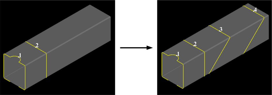
Set Tube Cutting
The tube cutting function is to generate cutting graphics on the tube for cutting tube parts.
Operating Steps:
On the 3D drawing Part Edit page, click Tube Cutting in the menu bar, and the cutting parameter pops up at the lower left corner, as shown in the following graphic:
Set translate, cliper and rotate parameters. See the following table for detailed parameter descriptions:
Parameter Description X offset The distance between the center of the cutting plane and the starting point of the main tube in the X axis direction. Y offset The distance between the center of the cutting plane and the starting point of the main tube in the Y axis direction. Z offset The distance between the center of the cutting plane and the starting point of the main tube in the Z axis direction. Left cliper Yes: the tube with Y axis coordinate less than the current cutting surface is scrap; No: The tube with Y-axis coordinates greater than the current cutting plane is scrap. X rotation angle The angle between the cutting plane and the YZ plane. Y rotation angle The angle between the truncation plane and the XZ plane. Z rotation angle The angle between the truncation plane and the XY plane. After setting, click Apply to add it to the Parts view area.
Insert Part
Insert a part on the spare tube in the tool path file without covering the tool path. support:
Insert File
On the current pipe, insert part tool path file and insert part position is:
- If the current tube has no part tool path, insert from the head of the tube.
- If the pre-process in 2D edit uses insert part space, the inserted part starts from the end of the existing part plus the set space position.
Insert part file format as .igs、.iges、.step、.stp。
Note: The inserted part tube type must be consistent with the current tube type and section size.
Operating Steps:
In the menu bar, click Common →
→ Insert File to open the Open dialog box: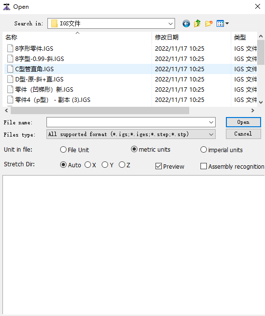
Select the part you want to import.
Set file unit and stretch direction.
Click Open, and the software will identify whether the tube type of the inserted part is consistent with the current tube type and section size.
Consistent: The part is inserted on the current tube.
Inconsistent: The Alarm/Log Message Bar prompts the cause of the error.
Insert 3D Wrapping
Insert a 3D wrapping graphic on the current tube at:
- If the current tube has no part tool path, insert from the head of the tube.
- If the pre-process in 2D edit uses insert part space, the inserted part starts from the end of the existing part plus the set space position.
The supported formats for wrapping graphics files are .g、.nc、.dxf、.dwg、.plt.
Operating Steps:
In the menu bar, click Common →
→ 3D Wrapping to open the Open dialog box: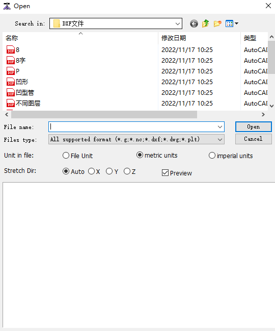
Select the file to import.
Set file unit and stretch direction.
Click Open.
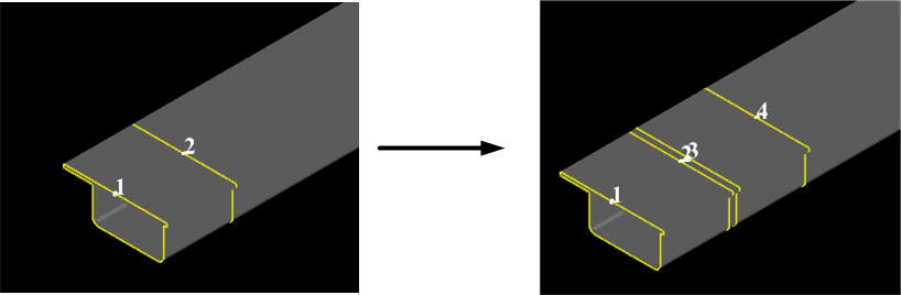
Effect picture:
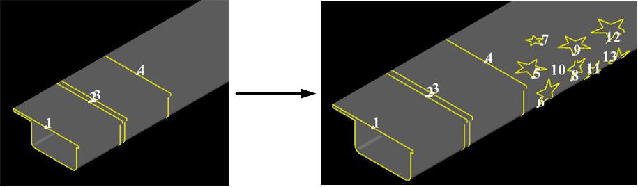
Insert Standard Part
Insert standard part of the same type of tube on the current standard tube at:
- If the current tube has no part tool path, insert from the head of the tube.
- If the pre-process in 2D edit uses insert part space, the inserted part starts from the end of the existing part plus the set space position.
In the menu bar, click Common →
→ Standard Part to open the Pipe Wizard dialog box: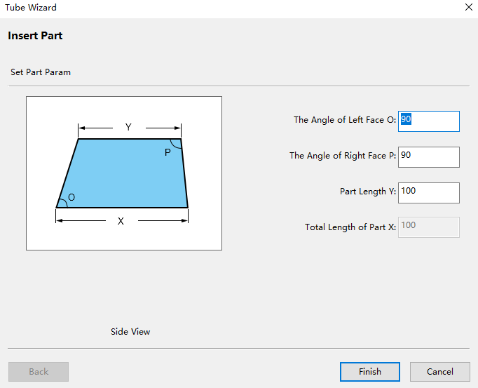
Set the part parameters. The left diagram shows the meaning of the parameters.
Click Finish.
Effect picture: