Quick Edit
In the 2D Edit page, the Quick Edit function button gathers common functions. The function entries are as follows: Quick Edit refers to the collection of common editing functions for the convenience of users. It provides the following functions:
- Tube Intersection
- Tube Cutting
- Tube Partition:The function entry is in the 2D Edit page.
- Tube Cutting Setting
- Part Mark:The function entry is in the 2D Edit page.
The function entries are as follows:
At the entrance of Software Main Interface
In the common toolbar of Software Main Interface, click
 Tube Intersection / Tube Cutting /
  Tube Cutting Setting.
At the entrance of the 2D Edit page
In the menu bar of the 2D Edit page, click Common →
 → Tube Intersection / Tube Cutting / Tube Partition / Tube Cutting Setting / Part Mark.
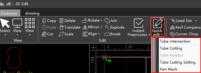
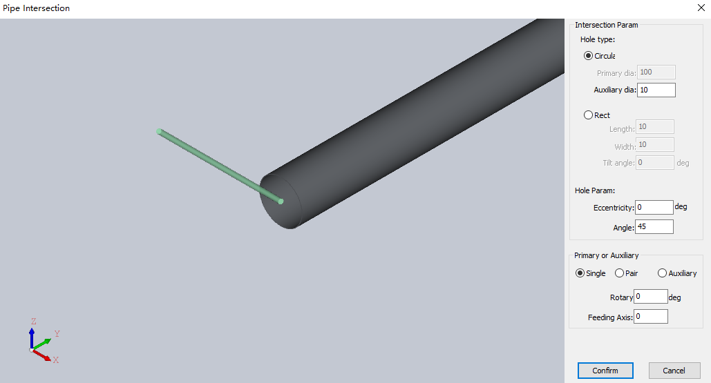
Tube Intersection
Generate intersecting hole tool path on tube, including circular hole and rectangular hole.
This section takes the intersection of circular tube as an example.
Operating Steps:
Select any of the following methods to open the Pipe Intersection dialog box:
- In the common toolbar of Software Main Interface, click Tube Intersection.
- In the menu bar of the 2D Edit page, click Common → → Tube Intersection.
- In the common toolbar of Software Main Interface, click
Select hole type and set hole param:
Parameter Description Circular Type of cut hole. Rect Type of cut hole. Primary dia The diameter of the main tube, that is, the diameter of the tube to be cut.
▪ When the cutting type is selected as Single or Pair, it cannot be set. The fixed value is the tube diameter.
▪ It can be set when the cutting type is selected as Auxiliary.Auxiliary dia The diameter of the branch tube, that is, the diameter of the tube that needs to run through the main tube. The setting shall meet the following requirements: branch tube diameter ≤ main tube diameter.
▪ It can be set when the cutting type is Single or Pair.
▪ When the cutting type is selected as Auxiliary, it cannot be set. The fixed value is the tube diameter.Eccentricity The distance between the main tube centerline and the branch pipe centerline. The maximum value should be ± (Main Tube Diameter - Branch Tube Diameter)/2. Angle The inclination angle when the main tube intersects the branch tube. Setting range: 5 º~175 º. In the Primary or Auxiliary area, set the following parameters:
Parameter Description Hole type You can select to generate Single, Pair or Auxiliary circular holes. Rotary The rotation angle of the cutting graphic relative to the workpiece origin. Feeding axis The feed axis distance of the cutting graphic relative to the workpiece origin. Click Confirm.
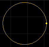
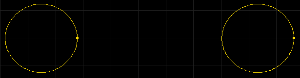
Effect picture:
Single
Pair
Auxiliary

Tube Cutting
Generate a cutoff path on the tube.
This section takes rectangular tube cutting as an example.
Operating Steps:
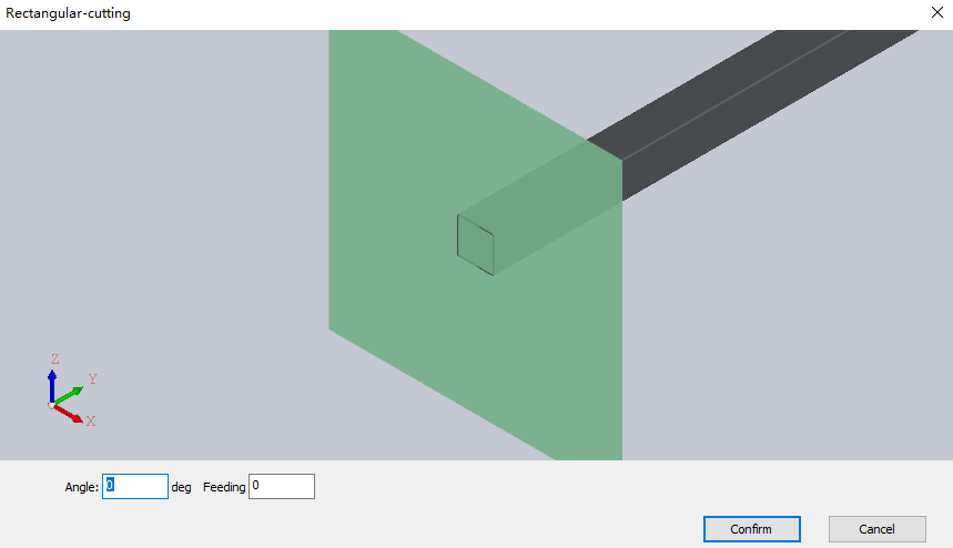
Select any of the following methods to open the Rectangular-cutting dialog box:
- In the common toolbar of Software Main Interface, click
 Tube Cutting.
 - In the menu bar of the 2D Edit page, click Common → → Tube Cutting.
- In the common toolbar of Software Main Interface, click
Set parameters for angle and feeding axis:
Parameter Description Angle The angle between the cutting surface and the tube centerline. Setting range: 5 º~175 º. Feeding Feed axis coordinates of the cutting position on the tube. Click Confirm.
Tube Partition
Generate intersecting and cutting array tool paths on tubes.
Operating Steps:
- In the menu bar of the 2D Edit page, click Common → → Tube Partition to open the Tube Partition dialog box:
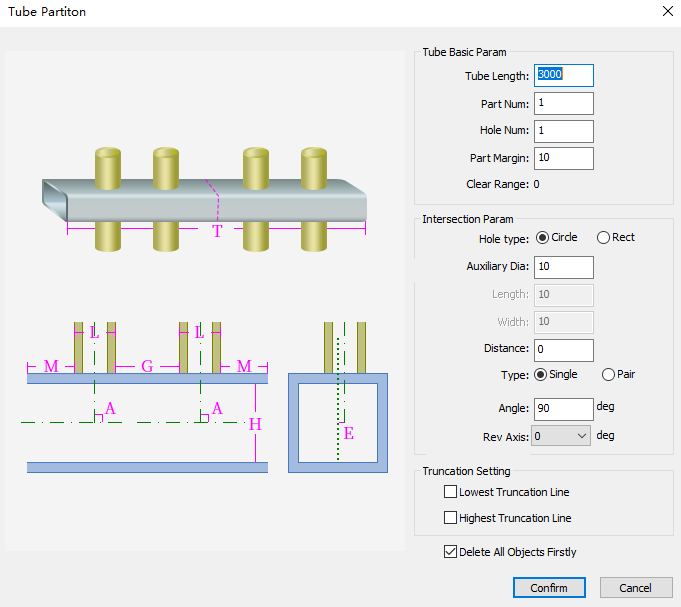
- In the Tube Basic Param area, set the following parameters:
| Parameter | Description |
|---|---|
| Tube length | Set the length of the tube. |
| Part num | The number of parts set on the tube. |
| Hole num | Number of holes per part. |
| Part margin | The distance reserved between parts. |
Note
Clear range: After setting the Tube Partition parameter, you need to ensure that the clear range is less than 0.
In the Intersection Param area, set the following parameters:
Parameter Description Hole type Select Circle or Rect. Auxiliary dia Circle parameter, the diameter of the branch tube, that is, the diameter of the tube that needs to run through the tube. Length Rect parameter, the length of the rectangular hole. Width Rect parameter, the width of the rectangular hole. Distance The distance between the tube centerline and the branch centerline. Type Optional when the cutting type is Circle. You can select to generate Single or Pair circular holes. Angle The inclination angle when the tube intersects the branch tube. Rev axis The rotation angle of the cutting graphic relative to the workpiece origin. Check the following options in the Truncation Setting area as required:
- Lowest truncation line
- Highest truncation line
Check Delete All Objects Firstly as required.
Click Confirm.
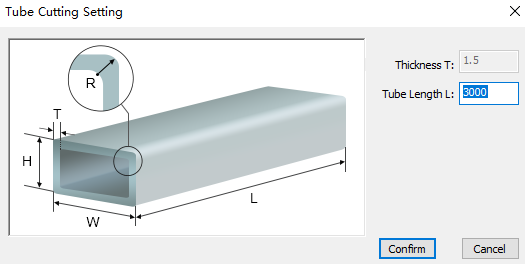
Tube Cutting Setting
Set the type and size of the machining tube in the software according to the actual situation.
This section takes rectangular tubes as an example.
Operating Steps:
Select any of the following methods to open the Tube Cutting Setting dialog box:
- In the common toolbar of Software Main Interface, click Tube Cutting Setting.
- In the menu bar of the 2D Edit page, click Common → → Tube Cutting Setting.
- In the common toolbar of Software Main Interface, click
Modify the tube length.
Click Confirm.
Part Mark
Modify the part name.
Operating Steps:
In the menu bar of the 2D Edit page, click Common →
 to check Show Part Mark.
Click
→ Part Mark to open the Part Mark dialog box: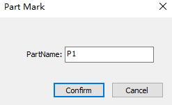
Set the part name.
Click Confirm, and the mouse becomes to
 .
.Click the line marked with the part to change the corresponding part name.
Click the right mouse button to exit the function.