Set Parameter
Parameter
System Parameter
This section describes how to find and modify system parameters by taking the modification of parameter Fixed Point Position (X) as an example.
Operating Steps:
In the menu bar, click Set →
 to open the System Parameter dialog box:
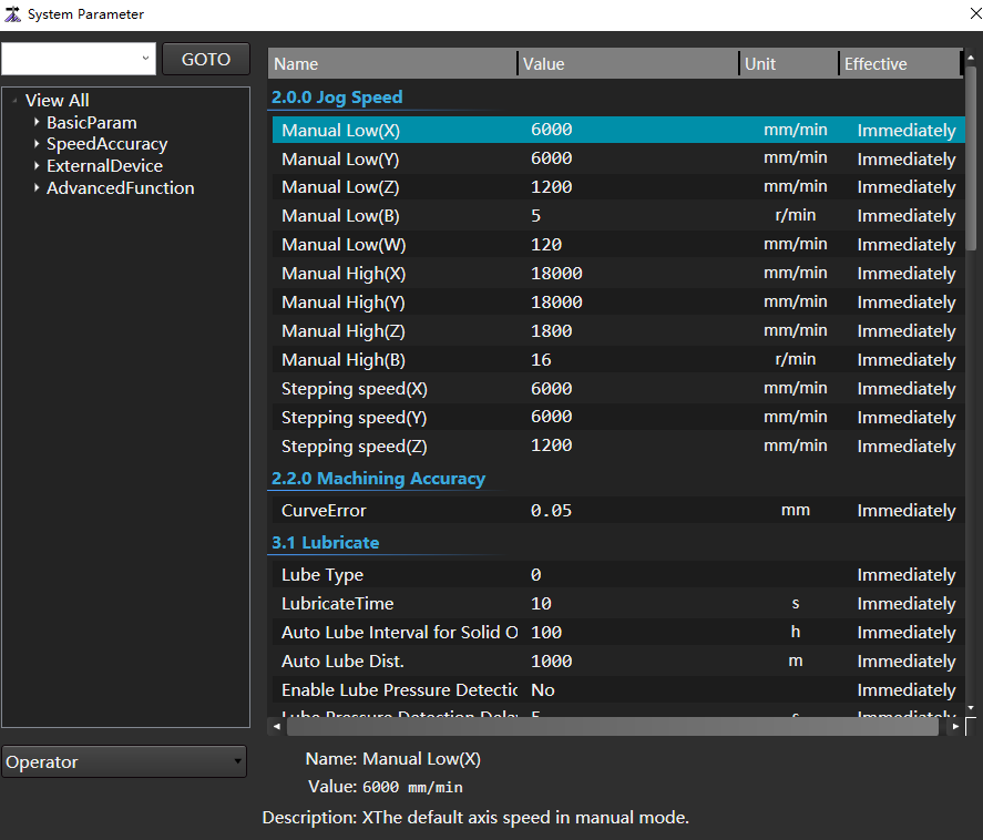
Use any of the following methods to find the Fixed Point Position (X):
- Search: In the search box, enter Fixed Point Position (X), click Go To, and the search results will be displayed on the right.
- Find through the node tree on the left: In the node tree, click View All → Advanced Function → 4.1 Fixed Point, and the parameters in the 4.1 Fixed Point node will be displayed on the right. Find the Fixed Point Position (X).
Double click the parameter Fixed Point Position (X) to pop up the Input Box:
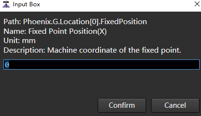
Enter value.
Click Confirm.
Port Setting
Monitor the condition of the machine tool by controlling the input and output ports, including conducting simulation tests, modifying port polarity, and setting port attributes.
General port settings are used to detect whether each port is effective during debugging, and change the port polarity according to actual needs.
The relationship between the machine tool condition and the input and output ports is as follows:
- Input port:
 With single;
  No single.
 - Output port:
 With single;
  No single.
When the port is in the test state, there is a T in the lower left corner of the signal, such as: 
Operating Steps:
In the menu bar, click Set →
 to open the Port Setting dialog box:
Select the port, and select the following operations according to the actual situation:
| Operation | Description |
|---|---|
| Click Test On or Test Off | Carry out simulation test, simulate opening or closing the port, and judge whether there is output by testing the port signal. The mark T in front of the port indicates that the port is testing. |
| Click Cancel Test | Cancel the test of the port. |
| Click Cancel All | Cancel the test of all ports. |
| Click Filtering | Set the filtering duration, and the system will exclude the signals whose occurrence time is less than this duration. |
| Click Modify Polarity | The polarity of the port changes to the opposite polarity. |
Lead Screw Compensation
When the machine tool itself has errors and cannot reach the expected accuracy, compensate the lead screw error to improve the machining accuracy.
Before using the lead screw compensation, click Set in the menu bar → ,to find and set the manufacturer's parameter Lead Screw Compensation Mode as not 0:
1:Backlash compensation only
2:Backlash compensation and unidirectional compensation
The compensation is made by printing the one-way data of the laser interferometer and the backlash value (printed by the dial indicator) set in the system parameters.
Its operation is consistent with that of using bidirectional compensation.
3:Bidirectional compensation
Compensate according to the bidirectional data of laser interferometer.
Use Backlash Compensation
Operating Steps:
In the menu bar, click Set →
to open the System Parameter dialog box:Select Manufacturer permission.
Click View All → Basic Param → 1.2 Error Compensation on the right to find the parameter Lead Screw Compensation Mode.
Double click Lead Screw Compensation Mode and enter 1 in the input box.
Click Confirm.
Use Bidirectional Compensation
Operating Premise:
The value of parameter Lead Screw Compensation Mode is 3.
Operating Steps:
In the menu bar, click Set →
 to open the Screw Comp. dialog box:
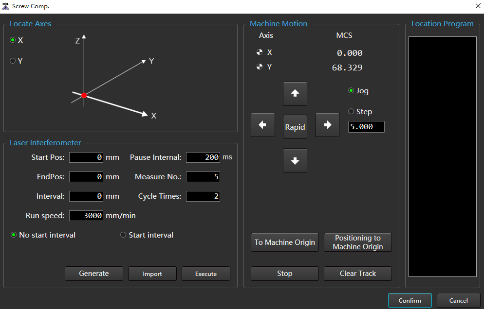
(Optional:) If X axis and Y axis need to return to mechanical origin, click To Mechanical Origin in the Machine Motion area.
Follow the steps below to get the actual measurement data of the machine tool:
In the Locate Axes area, select the locate axis.
Set the relevant parameters of the positioning program in the Laser Interferometer area, and click Generate. The results are automatically written into the Location Program area.
Click Execute, the machine tool starts to move according to the generated positioning program, and records the position data at the measuring point.
On the laser interferometer side, save the recorded position data as a
RTLorLINformat lead screw error compensation file.
Close the software and double-click NcTune under the file installation directory
C:\Program Files\Weihong\NcStudio\Binto enter the NcTune software.Click Screw Error to enter the Screw Error Compensation page.
Click Import to import the lead screw error compensation fileNcTune generates curves from files:
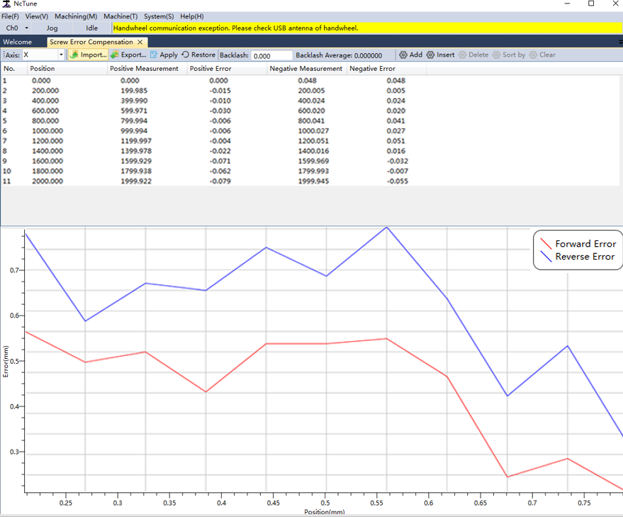
Red curve: Positive error;Blue curve: Reverse error.
Click Apply to automatically save the compensation data to the corresponding configuration file.
Restart the NcStudio software, and the compensation takes effect. During the system machining, the lead screw error is automatically compensated according to the compensation data.
Drive Parameter
Display the parameter value, unit, effective time and value range of driver parameters according to each axis, and support import, export and restore initial value settings.
Generally, during debugging, it is necessary to set basic driver parameters to drive the machine tool.
Operating Steps:
In the menu bar, click Set →
 to open the Drive Param dialog box:
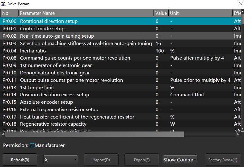
Perform the following as needed.
| If… | So… |
|---|---|
| View drive parameters | 1.In the drop-down key of axis, select the axis to view. 2. In the Show All drop-down button, select Show All or Show Common. |
| Import drive parameters | 1. Check Manufacturer permission. 2. Click Import to import a file in the format of .dat. |
| Export drive parameters | 1. Check Manufacturer permission. 2. Click Export to save all drive parameters locally in the file format of .dat. |
| Factory reset | 1. Check Manufacturer permission. 2. Click Factory Reset . |
| Refresh | Click Refresh. |
Laser Device Setting
The laser device settings are divided into:
Basic Setting: According to the type of laser driver, set the basic parameters, spot parameters and communication parameters of the laser driver.
QCW Mode Setting: If the peak power is much greater than the average output power of the laser driver, set the QCW mode to pulse mode.
Note
- If only basic settings are made, the QCW mode is continuous.
- When the QCW mode is pulse mode, the cutting parameter speed power and speed frequency curve functions will be shielded.
Adjust Laser AVC: Make the analog target output value of the laser consistent with the actual voltage.
The communication methods supported by each laser driver type include:
| Communication Mode | Raycus | IPG-YLR | YLR-K | Maxphotonics | SPI | IPG(US) | IPG(DE) | SUPER | Feibo | GW | JPT | Trumpf |
|---|---|---|---|---|---|---|---|---|---|---|---|---|
| Serial port | √ | √ | √ | × | √ | × | × | × | × | × | × | × |
| Internet port | × | √ | √ | × | × | √ | √ | × | × | × | × | × |
| Terminal board IO | √ | √ | √ | √ | √ | √ | √ | √ | √ | √ | √ | √ |
Basic Setting
Operating Steps:
In the menu bar, click Set →
 → Basic Setting to open the Basic Setting dialog box:
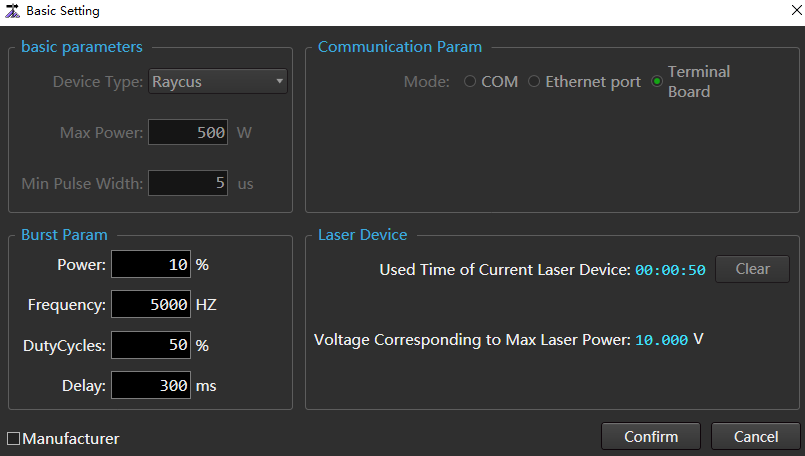
Check Manufacturer to activate the Basic Parameters area and Communication Param area.
In the Basic Parameters area, set the following basic parameters:
- Device type
- Max power
- Min pulse width
In the Communication Param area, select the communication mode.
In the Burst Param area, set the following click parameters:
- Power
- Frequency
- Duty cycle
- Delay
(Optional:) To reset the current laser driver service time, click Clear in the Laser Device area.
Click Confirm.
QCW Mode Setting
The continuous mode is the default mode. The QCW laser driver can switch the working mode of the laser driver to the pulse mode on this page.
Operating Premise:
Make sure that the relevant parameters have been set on the Basic Setting page.
Operating Steps:
In the menu bar, click Set →
→ QCW Mode to open the QCW Mode dialog box: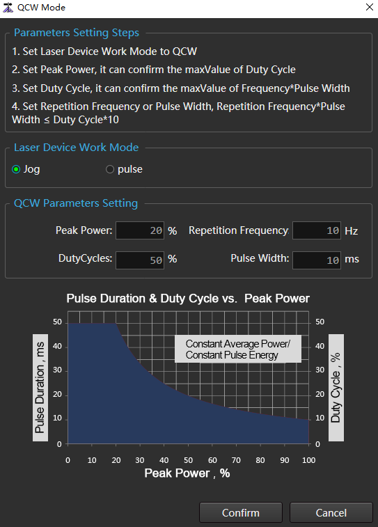
In the Laser Device Work Mode area, check Pulse.
Set parameters in the QCW Parameters Setting area:
- Peak Power
- Duty Cycle
- Repetition Frequency
- Pulse Width
Among:
Maximum input duty cycle=1000 ÷ peak power
Repetition frequency × pulse width ≤ duty cycle * 10
Click Confirm.
Adjust Laser AVC
Operating Steps:
In the menu bar, click Set →
→ Adjust Laser AVC to open the Adjust Laser AVC dialog box: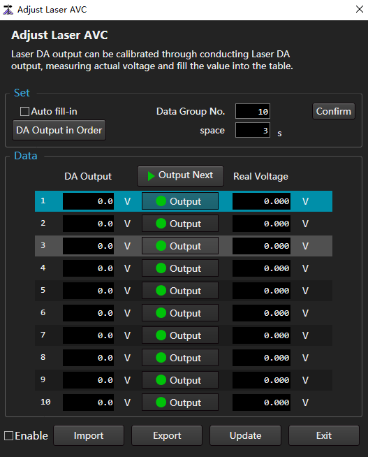
In the Set area, set the number of data groups and click Confirm.
By default, the number of data groups is 10. In the Data area, there are 0 to 9 rows of data.
Perform different operations according to different ways of filling DA Output column data.
- Auto fill-in: Check Auto Fill-in and click Confirm.
- Fill in manually: In the DA Output column, fill in the values in turn.
1.Perform different operations according to the way to fill in the Real Voltage column data.
Automatically output analog quantity according to the set time interval: Click the Space input box to input the set value, and click DA Output in Order in turn.
Fill in manually:
In the Data area, select the target data and turn on
 .
.Fill the actual measured voltage into the corresponding Real Voltage column.
- Enable.
- Check: Perform voltage correction. When the DA output data is inconsistent with the actual voltage data, it is recommended to check.
- Uncheck: No voltage correction is performed.
- Click Update.
Related Tasks:
- Export: Click Export to save the current data locally.
- Import: Click Import to import the locally saved data into the current Adjust Laser AVC dialog box.
Advanced
Feed Cutting
When machining to the end of the tube, the front chuck opens, and the rear chuck extends into the inside of the front chuck, so that the tube clamped by the rear chuck can be cut to save the tail length.
Operating Steps:
In the menu bar, click Set →
 to open the Feed Cutting dialog box:
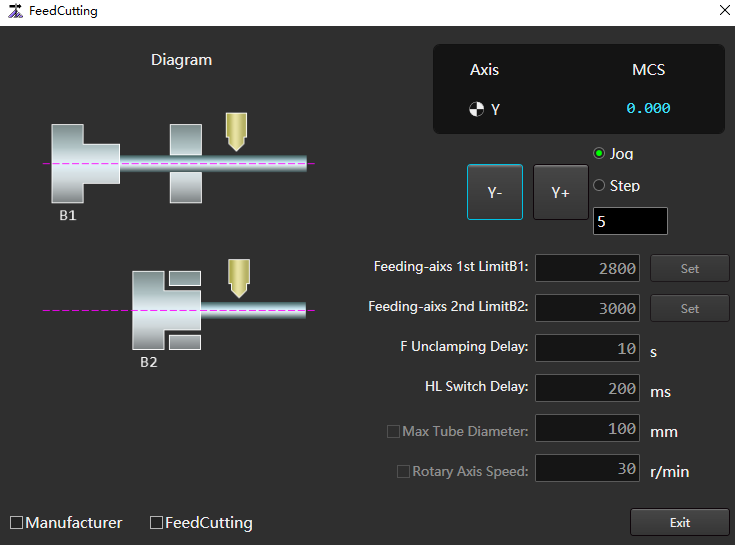
Check Manufacturer to activate parameters.
Sets the movement mode of the Y axis.
According to the different methods of setting parameters Feeding-axis 1st Limit B1 and Feeding-axis 2nd Limit B2, select the following operations:
Method Step Manual input 1.Click the corresponding input box to open the Input Box dialog box.
2. Enter value.
3.Click Confirm.Automatic input 1.Set the movement mode of Y axis: jog or step and the distance of one movement.
2.Click Y -/Y+ to move the Y axis to the mechanical coordinate position to be set.
3. Click Set corresponding to the parameter to automatically fill the mechanical coordinate of Axis Y into the input box.Enter values in the input boxes of parameters F Unclamping Delay and HL Switch Delay.
(Optional:) Check Maximum Tube Diameter / Rotary Axis Speed as required, and set parameter values in the input box.
Check Feed Cutting to enable this function.
Click Exit to complete the setting.
Pull Tube
The pull tube function is applied to the machine tool with short Y axis stroke. Through multiple pull tubes, the purpose of machining long tubes can be achieved
Operating Steps:
In the menu bar, click Set →
 to open the Pull Tube dialog box:
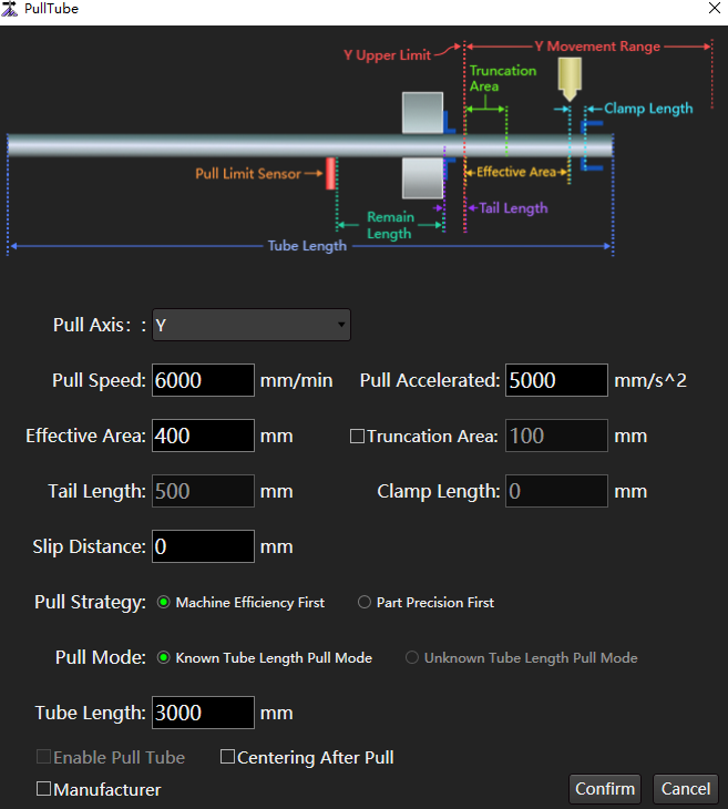
Check Manufacturer.
If you do not use the pull tube function after modifying the parameters, uncheck Enable Pull Tube.
Set parameters. The parameters are described as follows:
Please refer to the schematic diagram of the Pull Tube dialog box.
| Parameter | Description |
|---|---|
| --- | --- |
| ---- | ---- |
| Pull axis | Select different pull axis according to different machine tool designs: ▪ Y axis: The rear chuck pusher, that is, the model with the cutting head stationary and the rear chuck driving the tube movement. ▪ Extended axis: The front chuck pull tube machine tool, that is, the machine with cutting head moving and tube not moving. |
| Pull speed | The speed at which the tube is pulled on the Y axis. |
| ---------- | ---------------------------------------------------- |
| Pull accelerated | The acceleration of tube pulling on the Y axis. |
| Effective area | ▪ When the rear chuck is clamped at one end, the machining accuracy of the front end of the tube is poor, ensuring that all graphics are cut in this area. ▪ The length of a single part to be machined cannot exceed this parameter. If it exceeds this parameter, it cannot be machined. ▪ Generally about 100 mm. ▪ The actual position is, [upper limit, upper limit - effective area] For example, if the upper limit is 3000, the actual machining position is 2900-3000. |
| Truncation area | Under the single end clamping state of the rear chuck, the machining accuracy of the front end of the tube is poor, so that all truncation lines are cut in this area. |
| Tail length | When the Y axis is at the upper limit, the distance from the cutting head to the end of the tube when the tube can be clamped. |
| Clamp length | It shall be set according to the position of the collet to prevent clamping. ▪ The collet extends beyond the left end of the cutting head and is set to 0. ▪ The collet is located flush with the cutting head and set to a positive value, generally 10-20 mm. |
| Slip distance | Supplementary distance given to prevent skidding during pull tube. |
| Pull strategy | ▪ Machining efficiency first: Ensure the machining efficiency, and reduce the number of pull tube as much as possible. ▪ Part precision first: Try to ensure that the cutting of a single part is completed after once pull tube. |
| Pull mode | ▪ Know tube length pull mode: This mode is selected when the length of the tube to be cut is known. ▪ Unknow tube length pull mode: This mode is selected when the length of the tube to be cut is unknown. Note: This option can be selected only after the port Pull limit is configured in the ncConfig application. |
| Tube length | The length of the tube to be machined. It takes effect when the pull mode is Know Tube Length Pull Mode. |
Check as needed:
- Enable Pull Tube: If you do not use the pull tube function after modifying the parameters, uncheck Enable Pull Tube.
- Centering after Pull.
Click Confirm to complete the setting.