System Maintenance
Automation
Set Auto Load Parameter
When auto loading is executed, the system executes according to the set parameters.
Operating Steps:
In the menu bar, click Maintain →
 to open the Auto Load dialog box:
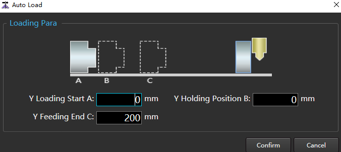
Set the load parameter according to the meaning of the schematic diagram and the actual situation.
Click Confirm.
Related Tasks:
To enable the automatic loading function, configure it in NcConfig → Configuration → Process Edit.
Set Tube Length
Set the current tube length for auto load, calculate the clamping position of the rear chuck, and set the maximum tube length, that is, the distance from the end position of the tube clamped by the rear chuck to the lower part of the cutting head when the pull axis machine is 0.
The pipe length setting requires the manufacturer's password.
Operating Steps:
In the menu bar, click Maintain →
 to open the Set Tube Length dialog box:
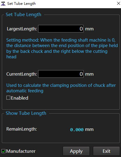
Check Manufacturer.
Set the parameters Largest Length and Current Length.
Check Enabled.
Click Apply.
Tail Material Processing Setting
The system provides 6 unloading actions. The user can set the length of different tailings and execute different unloading actions. Up to 6 tailing lengths can be set.
Operating Steps:
In the menu bar, click Maintain →
 to open the Tail Material Processing Setting dialog box:
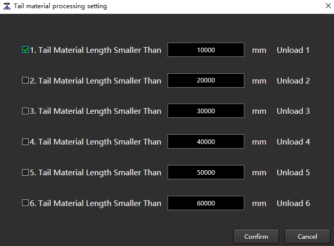
Set the tailing length.
Check the items that need to be enabled.
Click Confirm.
Related Tasks:
To enable the tail material processing function, you need to configure it in NcConfig → Configuration → Process Edit.
Part Collection Setting
The system provides 6 part collection actions. You can set the length of different parts and perform different parts collection actions.
Operating Steps:
In the menu bar, click Maintain →
 to open the Part Collection Setting dialog box:
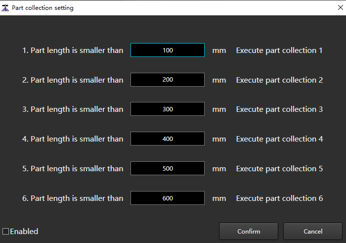
Sets the part length.
Check Enabled.
Click Confirm.
Related Tasks:
To enable the part collection function, you need to configure it in NcConfig → Configuration → Process Edit.
External Device
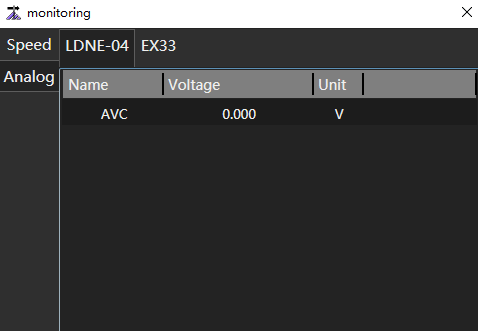
Monitoring
Real time monitoring of the following information:
- Motion speed of each axis
- Port voltage value of Lambda controller and expansion board
Operating Steps:
In the menu bar, click Maintain →
 to open the Monitoring dialog box:
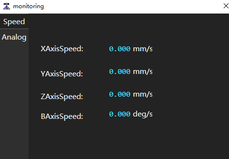
Click Analog to switch pages to view the Lambda controller and expansion board.
Laser Monitor
Check the status of the laser driver, such as power, temperature, water flow, mode, alarm, etc.
Operating Premise:
- Make sure that the laser driver is in good condition.
- Ensure that NcStudio software communication is normal.
Operating Steps:
In the menu bar, click Maintain →
 :
:- If there is a specific path in the Laser Device Program Path of the system parameter Advanced Function Parameter → Laser Device Path, directly open the upper computer software of the laser.
- If the parameter Laser Device Program Path does not exist, the file selection dialog box will pop up to select the path of the upper computer software of the laser device.
Lubricate Screw
The lead screw shall be lubricated after the machine tool runs for a period of time.
There are two methods:
Auto: The system can automatically perform lubrication during machining according to the set parameters by setting parameters.
Manual: Manually control the machine tool to perform lubrication.
Operating Steps:
Auto
In the menu bar, click Set →
 to open the System Parameter dialog box:
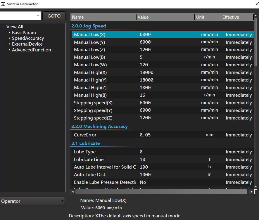
In the parameter tree on the left, select the node View All → External Device → 3.1 Lubricate. Lubrication parameters and parameter information are displayed on the right:
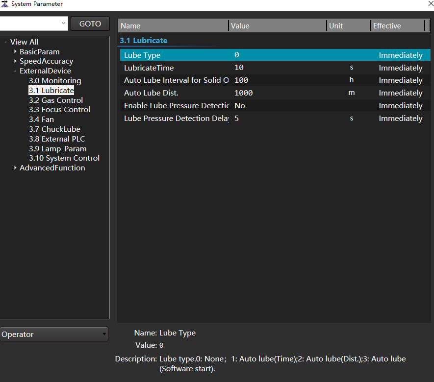
Set manufacturer parameters Lube Type :
- 0:Do not enable auto lube
- 1:Auto lube (time)
- 2:Auto lube (distance)
Set the following parameters according to the selected lubrication type:
Lubricate Time
Auto Lube Interval for Solid Oil Pump: Set when the lubrication type is Auto Lube (Time).
Auto Lube Dist.:Set when the lubrication type is Auto Lube (Distance).
Enable Lube Pressure Detection
Lube Pressure Detection Delay
After setting, the auto lube interval for solid oil pump/auto lube distance interval of the system every time. Auto open lube port duration Lubricate Time.
Manual
In the menu bar, click Maintain →
 to open the Lube dialog box:
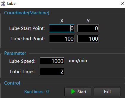
Set the corresponding parameters.
Click Start, and the system starts to execute lubrication action, and displays the lubricated times.
Tube Support Debugging
Set the running strategy of the tube support and debug whether the tube support is running properly.
Click on the Machine Tool Control Bar  . Enable or shield tube support.
Operating Steps:
In the menu bar, click Maintain →
 to open the Tube Support Debugging dialog box:
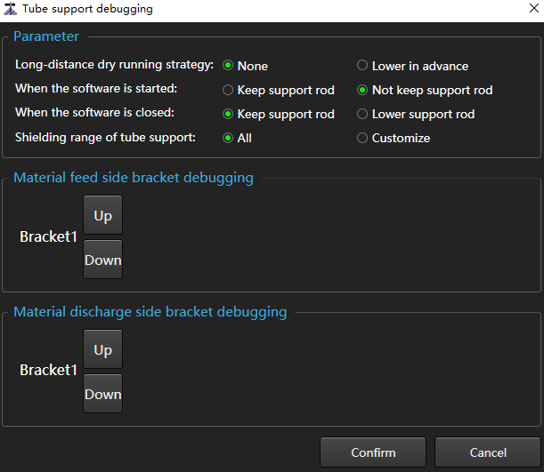
In the Parameter area, set the action strategy.
Click Up or Down to debug the equipment in the Material Feed Side Bracket Debugging area and Material Discharge Side Bracket Debugging area.
After debugging, click Confirm to exit.
Servo Carrier Shaft Debugging
Term:
- Carrier mechanism: On the tube cutting machine, the mechanical structure supporting the tube.
- Servo carrier: A carrier mechanism that uses a servo motor to dynamically adjust the highest point position of the carrier mechanism.
- Bed roller carrier: The carrier mechanism is at the feeding side.
- Blanking roller carrier: The carrier mechanism is at the blanking side.
Function of Servo Carrier:
When machining long and thin tubes, when the chuck rotates, the tubes will sag, deform and shake, which will affect the machining safety and machining accuracy. The servo carrier mechanism can solve the problem well. The principle is that the highest point of the carrier mechanism is always just in contact with the lowest point of the pipe when the chuck is rotating or when the chuck is stationary.
This section takes the bed roller carrier as an example to introduce the debugging methods and steps of the servo carrier.
Operating Premise:
- Chuck debugging has been completed.
- The feeding shaft and servo carrier shaft are debugged and can move normally.
- The servo carrier shaft has finished returning to the mechanical zero point, or the reference has been set.
- The support cylinder can work normally.
Operating Steps:
Adjust the movement direction of the Servo Carrier Shaft to ensure that when the Servo Carrier Shaft moves in the positive direction, the Carrier Highest Point rises and the reverse movement decreases.
- In the menu bar, click Set → to open the System Parameter dialog box.
- In the node tree, click the Show All → Basic Param → 1.0 Axis Param node.
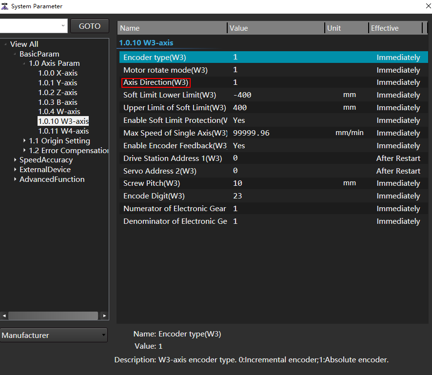
- In the menu bar, click Set →
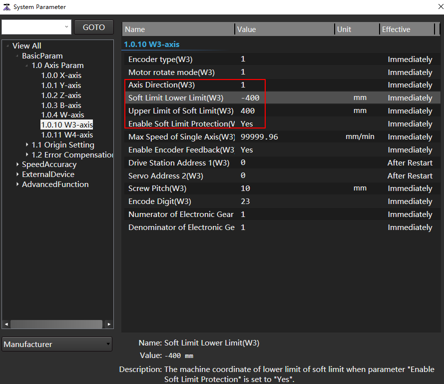
Set the positive and negative soft limits of Servo Carrier Shaft to ensure that the position of Carrier Highest Point will change when Servo Carrier Shaft moves.
The purpose of this step is to ensure that when the Support Cylinder is supported, the Carrier Highest Point position is completely adjusted by the Servo Carrier Shaft.
- In the node tree, click the Show All → Basic Param → 1.0 Axis Param node.
- In the 1.0 Axis Param parameter column, adjust the positive and negative soft limit of Servo Carrier Shaft, and enable the soft limit protection.
When the Servo Carrier Shaft moves in a 5mm step, record several groups of Carrier Highest Point height values.
In the menu bar, click Maintain →
 to open the Servo Roller Debug dialog box:
In the Locate area, click the + button to make the W axis (servo carrier shaft) move near the upper limit of its soft limit, and the Carrier Highest Point is at the highest position.
Record the value of Carrier Highest Point at the highest position.
Check Step, switch to step mode, and set the step size to 5.
Click the - button and record the corresponding Carrier Highest Point until the W axis (servo carrier shaft) moves to the lower limit of its soft limit.
For example: The following table shows the debugging data of a customer.
W3 Axis Step Size Carrier Highest Point Change of Carrier Highest Point 5 172.5 - 5 169.1 3.4 5 164.8 4.3 5 160.7 4.1 5 156.4 4.3 5 164.8 4.3 5 160.7 4.1 5 156.4 4.3 5 152.1 4.3 5 147.8 4.3 5 143.6 4.2 Calculate the average value of carrier highest point change.
For example, in the above table, when the W3 axis (servo carrier shaft) step is 5mm, the average change of Carrier Highest Point is (4.3+4.1+4.3+4.3+4.2)/6=4.25. Note, that discrete data records must be discarded in this step, such as 3.4 in the table above.
Calculate the ratio between the average change value of Carrier Highest Point and the movement step size of Servo Carrier Shaft.
For example, in the above table: K = 4.25 / 5 = 0.85
Adjust the Servo Carrier Shaft pitch according to the ratio between the average value of Carrier Highest Point change and the Servo Carrier Shaft motion step.
New Servo Carrier Shaft pitch=original Servo Carrier Shaft pitch * K
According to the above calculation, the screw pitch is adjusted from 10 to 8.5.
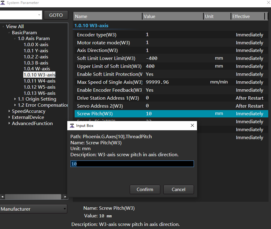
Perform Servo Carrier Shaft calibration or homing, and reset the upper and lower limit values of the Servo Carrier Shaft soft limit.
Note
This step is because the screw pitch of Servo Carrier Shaft has been adjusted.
Repeat step 3 (step 4, step 5, step 6 and step 7 will not be executed), and verify whether the Servo Carrier Shaft moves 1mm and the Carrier Highest Point height changes 1mm after adjusting the Servo Carrier Shaft pitch.
For example: The following is the data of a customer's machine tool after adjusting the Servo Carrier Shaft pitch.
W3 Axis Step Size Carrier Highest Point Change of Carrier Highest Point 5 172.5 - 5 167.8 4.8 5 162.7 5.1 5 160.7 4.1 5 157.4 5 5 152.9 4.8
Note
Description: If the Servo Carrier Shaft pitch is adjusted, the Servo Carrier Shaft moves for 1mm, and the height change of the Carrier Highest Point differs greatly from 1mm, step 3 must be repeated (step 4, step 5, step 6 and step 7 must be performed at the same time).
Use circular tube calibration.
Manually install a standard circular tube.
In the menu bar, click Common→
 → Tube to Open the Tube Wizard dialog box.
Select the circular tube and open the Set Section Param dialog box:
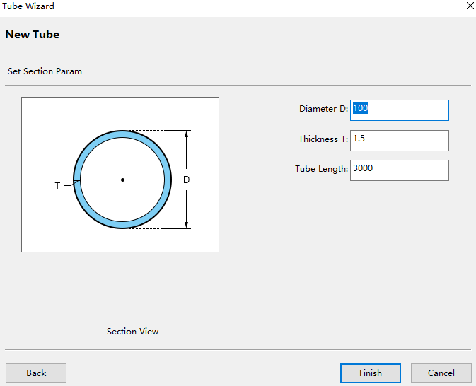
Set the tube section parameters. Note that the direct and thickness should be consistent with the current pipe on the machine tool.
Ctr+s or click the Save button to save the machining file.
In the menu bar, click Maintain →
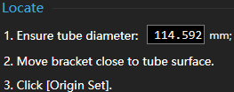
to open the Servo Roller Debug dialog box.Calibration: In the Locate area, complete the calibration.
Set the follow mode. In the Mode area, select Follow Mode.
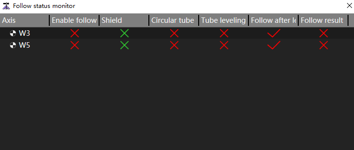
In the Servo Roller Debug dialog box, click Follow Status Monitor at the bottom left corner. In the Follow Status Monitor dialog box, check whether the current follow takes effect normally, and the specific reason why it does not take effect.
Click Save to finish debugging.
Caution
In consideration of pipe sagging, it is recommended that the carrier highest point close to the chuck should be 1~3mm away from the lower surface of the tube during calibration to avoid the carrier from pressing the tube out of the indentation during normal machining after commissioning.
Adjust Air Pressure
Adjust air pressure means to correct the analog output of gas, so that the actual air pressure is consistent with the analog output.
DA refers to converting digital quantity into analog quantity.
Operating Steps:
In the menu bar, click Maintain →
 to open the Adjust Air Pressure dialog box:
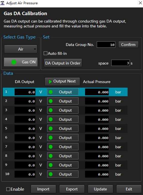
In the Select Gas Type area, select the target gas.
In the Set area, set the data group no. and click Confirm.
By default, the number of data groups is 10. In the Data area, there are 0 to 9 rows of data.
Perform different operations according to different ways of filling DA Output column data.
- Auto: Check Auto Fill-in and click Confirm.
- Manual: In the DA Output column, fill in the values in turn.
Perform different operations according to the way to fill in the Actual Pressure column data.
Automatically output analog quantity according to the set time interval: Click the Space input box to input the set value, and click DA Output in Order in turn.
Manual:
In the Data area, select the target data and turn it on
 , Select Gas Type area
 is highlighted, gas output.
The current display value of the proportional valve is the actual air pressure value.
Fill the displayed value of the proportional valve into the corresponding Actual Pressure column.
Enable.
- Check: Do adjust air pressure. It is recommended to check when the DA output data is inconsistent with the actual air pressure data.
- Uncheck: Do not adjust air pressure.
- Click Update.
Related Tasks:
- Export: Click Export to save the current data locally.
- Import: Click Import to import the locally saved data into the current Adjust Air Pressure dialog box.
Focus Calibration
Correct the focus so that the position distance is consistent with the analog output.
Operating Premise:
Before correcting the focus, set the following parameters and restart the software:
Set the parameter Enable Focus Control to Yes to enable the focus control function.
Set the parameter Focus Control Type to Precitec Auto Focus.
Operating Steps:
In the menu bar, click Maintain →
 to open the Focus Calibration dialog box:
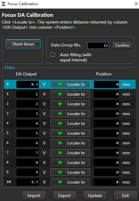
Select Short Focus or Long Focus according to the cutting head specification.
Enter a value in Data Group No. and click Confirm.
By default, the number of data groups is 10. In the Data area, there are 0 to 9 rows of data.
Perform different operations according to different ways of filling DA Output column data.
- Auto: Check Auto Filling and click Confirm.
- Manual: In the DA Output column, fill in the values in turn.
In the Data area, select the target data and turn on
 .
.Connect the cutting head through bluetooth and fill the data viewed on the Precitec Procutter mobile phone software into the corresponding Position column.
Click Update to complete the focus calibration.
Related Tasks:
- Export: Click Export to save the current data locally.
- Import: Click Import to import the locally saved data into the current Focus Calibration dialog box.
Tool
Reconnect Manually
It is applicable to the system with bus configuration. After the communication between the system and the drive is disconnected, the communication with the drive can be reestablished through manual reconnection.
Operating Steps:
- In the menu bar, click Maintain →
 .
.
Jiggle of Multiple B Axes
Juggle rotation axis provides an independent and quantitative control means for double rotation axis. According to the actual synchronous deviation of the two rotating shafts, the feedback coordinates of the two rotating shafts can be adjusted to be consistent to complete manual correction.
Operating Steps:
In the menu bar, click Maintain →
 to open the Jiggling of Multiple B Axes dialog box:
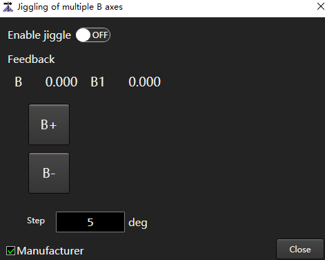
Set Enable Jiggle to the ON state.
Click the step input box to set the step distance of jiggle.
The default is 5.
Click B+ / B- / B1+ / B1-. Adjust the feedback coordinates of axis B or B1.
One-click Cutoff
One-click cutoff. Use large graphic technic to cutoff at the current Y axis coordinate position.
Warning
The section that is forbidden to be executed is not closed or irregular tube, otherwise there is danger.
Operating Premise:
Ensure that the section of the current machining document is consistent with the actual clamped tube.
Operating Steps:
In the menu bar, click Maintain →
 to open the One-click Cutoff dialog box:
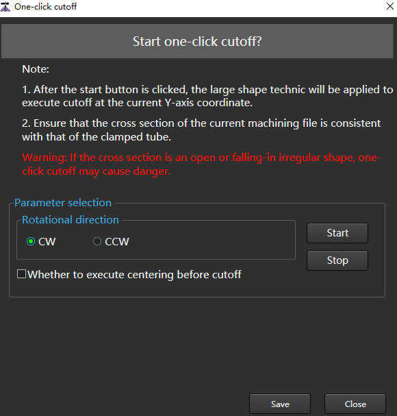
Select the rotational direction.
Check Whether to Execute Centering Before Cutoff as required.
Click Start to pop up a prompt box:
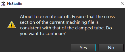
Click Yes to start the cutoff operation.
Custom Instructions Debug
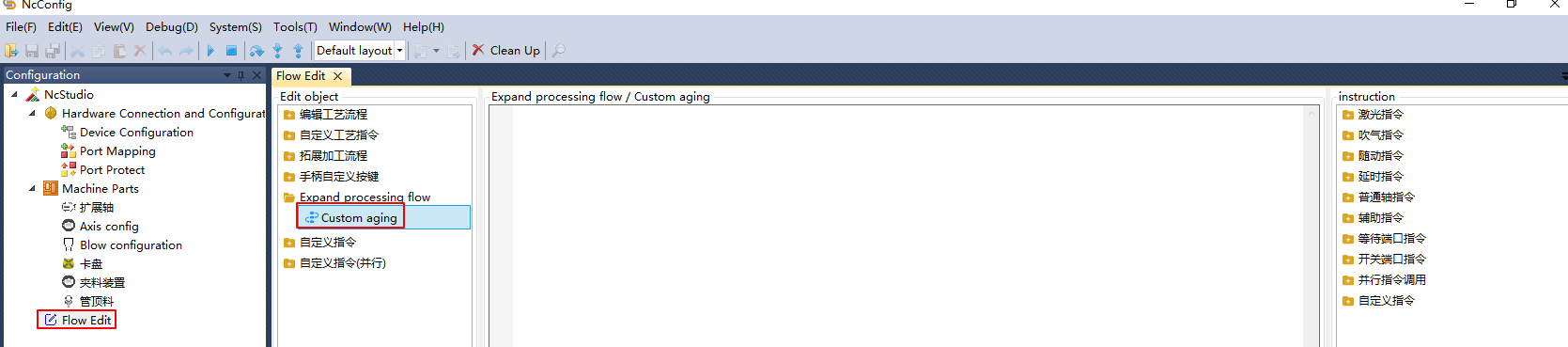
Whether the custom instructions debug are reasonable. The customized instructions are configured in NcConfig → Configuration → Flow Edit.
Caution
If the process is written incorrectly, the machine tool may be damaged. Please stop debugging in time when executing.
Operating Steps:
In the menu bar, click Maintain→
 to enter the manufacturer password and open the Custom Instructions Debug dialog box:
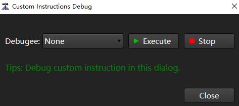
Select the instruction in the Debugee drop-down box.
Click Execute to check whether the instruction is reasonable.
Disable Action of Flow Edit
Disable or enable action of flow edit to include user defined instructions.
Operating Steps:
In the menu bar, click Maintain →
 to open the Disable Action of Flow Edit dialog box:
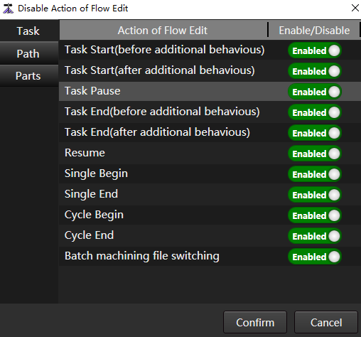
The actions in the General tab are user defined instructions.
Disable or enable action of flow edit as required.
- Disable: That is, the button is set to the
 state.
 - Enabled: That is, the button is set to the
 state.
- Disable: That is, the button is set to the
After setting, click Confirm.
Trial Run
At the initial commissioning stage of the machine tool, trial run is required to ensure the stability of the motion of each axis of the machine tool.
The system provides two methods:
User defined trial: used for external devices such as aging chucks. The action executed is the command action of the User Defined Trial configuration edited by the process.
The instruction action configuration entry is: NcConfig application Configuration → Flow Edit object Custom Aging.
Axis aging: Used for the movement of each axis of aging machine tool. Configure shaft parameters and control aging time through the Trial Run dialog box to start aging.
Operating Premise:
To ensure the safety of the machine tool, before aging the machine tool, make sure that all axes have executed Execute Return to Mechanical Origin or Set Datum.
Operating Steps:
In the menu bar, click Maintain →
 to open the Trial Run dialog box:
Depending on the method selected, select to perform the following operations:
- If you select custom aging, check Enabled in the Custom Aging area.
- If axis aging is selected, select the axis to be aged in the Axis area, and set the starting/ending position and the first/second/third stage speed of aging.
In the Control area, set the time of the first/second/third aging stage.
At the bottom of the dialog box, check Block Safety Door Alarms and Shield Collision and Cutting Head Alarm as required.
Warning
There is a risk of cutting head collision, please use with caution!
Click Start, and the machine tool begins to age.
During machine tool aging, click Stop to stop machine tool aging.
Related Tasks:
To view the machine tool aging history, click History.
MDI
The user can freely input and execute up to seven simple programming instructions in this area to realize rapid movement, change the system state or carry out simple machining.
Operating Steps:
In the menu bar, click Maintain →
 to open the MDI dialog box:
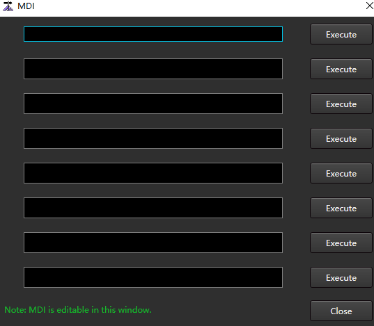
Select the target command line, enter the command in the input box, and use ; (semicolon) to wrap.
Click Execute corresponding to the line, and the system will automatically execute the entered instructions.
Machine Maintenance Regular Reminder
The machine maintenance regular reminder function can set the maintenance cycle. When the specified cycle is reached, the system will automatically pop up a prompt box to remind the user to maintain the machine tool.
The maintenance cycle can be set according to the time cycle or the running distance of the machine tool.
On the machine maintenance regular reminder page, reset, edit, add and delete functions are also provided.
Operating Steps:
In the menu bar, click Maintain →
 to open the Machine Maintenance Regular Reminder dialog box:
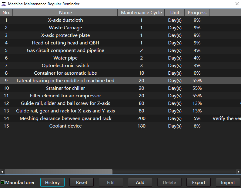
Check Manufacturer.
Click Add to pop up the Add dialog box:
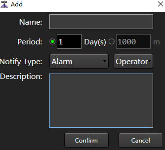
Set parameters as required. The parameters are described as follows:
| Parameter | Description |
|---|---|
| Name | The name of the maintenance item must be unique. |
| Period | Either time/distance period. ▪ Time period description: How many days should the maintenance be carried out; The number of days is the world time obtained by computer. ▪ Distance period description: The machine tool needs to be maintained every few meters; The distance adopts the machine tool movement distance. |
| Notify type | Either alarm/notification. ▪ Alarm: The progress is displayed in red, and the alarm dialog box pops up. ▪ Notification: The progress is displayed in red and a "warning" log is generated. |
| Description | The service items were described and the maintenance contents were required to be clarified. There was no misunderstanding. |
- Click Confirm.
Related Tasks:
- Modify an existing maintenance item: Select the target item and click Edit.
- Restore the set value of the existing maintenance item to the initial value: Click Reset.
- Delete maintenance Item: Select the target item and click Delete.
Encoder Detection
It is used to detect whether the encoder feedback is consistent with the motor rotation mode, and automatically calculate the PG frequency division ratio, so as to avoid affecting the second-generation flying cut and follow-up effects, and the inconsistency between the actual coordinates of the machine tool and the software coordinates under the non servo alarm E-stop state.
Only applicable to non bus control systems.
Operating Premise:
- The drive parameters are set correctly.
- The pulse equivalent of each axis, axis direction and the number of command pulses per cycle have been set correctly.
- The X axis and Y axis have been moved to the middle of the machine tool stroke, and there is enough stroke for detection.
Operating Steps:
In the menu bar, click Maintain →
 to open the Encoder Detection dialog box:
(Optional:) Set XY moving distance in the Set area.
The default distance is 10mm, which is generally set as a long pitch to minimize the error of detection.
In the Control Panel area, click Start.
If Automatically Write Detection Values after Detection is checked, the feedback data results will be automatically written into the system parameters.
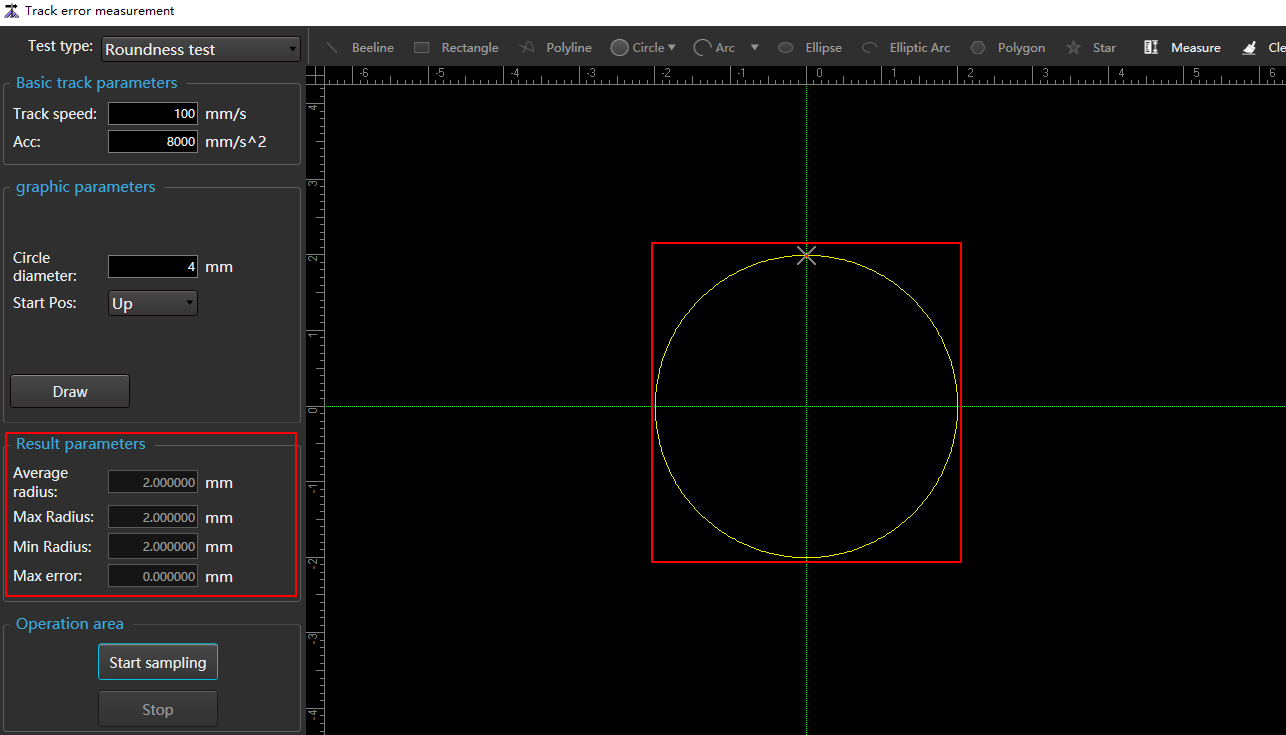
Track Error Measurement
Through multi axis linkage, the difference between transmission and feedback tracks is displayed, which is the basis for subsequent adjustment of driver parameters.
Operating Steps:
In the menu bar, click Maintain →
 to open the Encoder Detection dialog box:
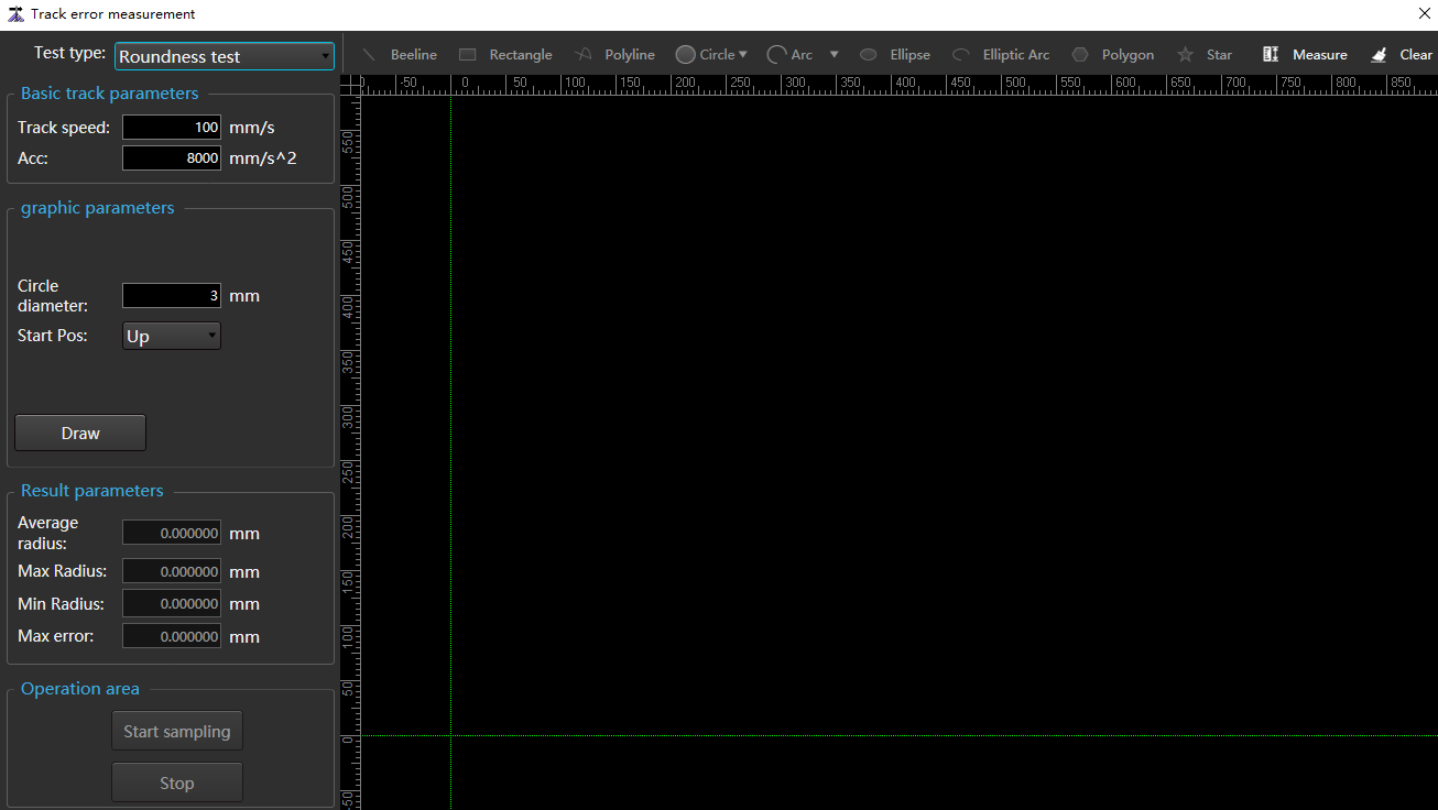
Set track speed in the Basic Track Parameters area.
Set graphic.
- Select a graphic type from the Test Type drop-down box.
- Depending on the selected graphic, do the following:
The test type is Roundness Test or Rectangularity Test:
- In the Graphic Parameters area, set parameter information.
- Click Draw to display the corresponding graphic in the middle drawing area.
The test type is Custom Track Test:
- Draw: Click the corresponding graphic button in the Track Error Measurement dialog box, and then draw a graphic in the drawing area.
- Import: In the Graphic Parameters area, click Import DXF to select a file.
Click Start Sampling, and you can see the test track in the Track Error Measurement dialog box. If the measurement type is Roundness Test, the results are displayed in the Result Parameters area.
Effect picture:
Extended Axis Commissioning
Adjust the movement and speed of the extension axis.
Operating Steps:
In the menu bar, click Maintain →
 to open the Extended Axis Commissioning dialog box:
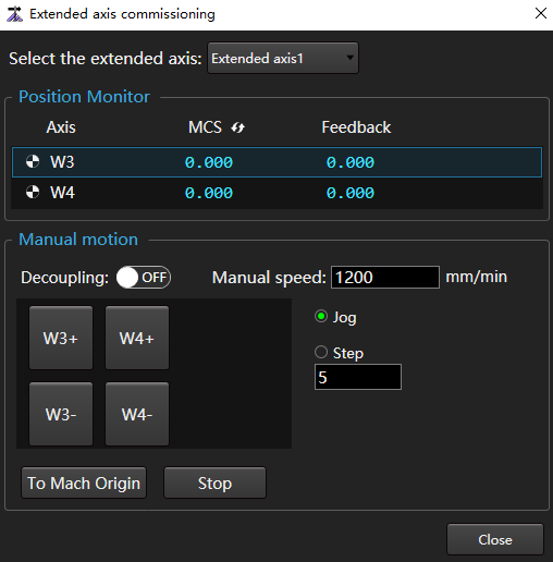
In the Select the Extended Axis drop-down box, select the extension axis to debug.
In the Manual Motion area, set the speed and the movement mode of the extension axis.
Click W1+, W1 -, To Mach Origin, Stop according to the debugging requires, and judge whether the extension axis moves normally by observing the mechanical coordinate and actual axis movement in the Position Monitor area.