Common Operation
Set Workpiece Origin
The zero point of each axis in the tool path is the workpiece origin. Before machining, it is necessary to determine the actual position of the workpiece origin on the workpiece.
Operating Steps:
On the machine tool control bar, click X+ / X- / Y+ / Y- / B+ / B- button to move the cutting head to the target position.
In the machine tool control bar, click
 or press the F5 key to set the current position as the workpiece origin.
Calibrate Cutting Head
The purpose of calibrating the cutting head is to measure the capacitance and position relationship between the cutting head and the plate, so as to control the Z axis up and down floating in real time. To ensure that the relative distance between the cutting head and the plate remains unchanged under the follow up state.
Operating Steps:
In the menu bar, click Common →
 to open the Follow-up Control dialog box:
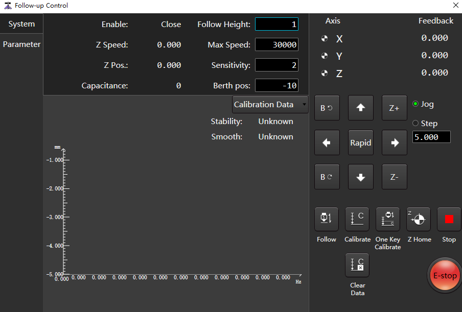
Click
 Follow to open the follow-up valve.
Click
 Calibrate to calibrate the servo, solve the problem of servo motor zero drift caused by speed loop control, and the system automatically generate the value of parameter Servo Compensation.
According to the actual situation, select the following methods, move the cutting head to about 5mm near the plate surface, and keep the plate surface still all the time:
If the cutting head has not been calibrated, click the Z-axis direction button, move the cutting head to about 5mm on the board surface, and keep the board still all the time. In the machine tool control bar, click
 to calibrate the cutting head.
If the cutting head has been calibrated, click
 One Key Calibrate on the Follow-up Control page.
The system automatically perform calibration, which take about 20s to complete.
After calibrating the cutting head, view it in the Calibration Data area of the Follow-up Control dialog box:
- If Stability and Smooth are higher than Good, continue normal machining.
- If Stability and Smooth are lower than Good, need to recalibrate.
Tube Edge Find
By moving the feed axis, the cutting head is positioned exactly above the tube section.
The process of edge finding is as follows:
The laser head follow-up axis follows to the following height once.
Calibrate before use.
The cutting head move along the negative direction of the feed axis and stop when it reaches the edge of the tube.
Caution
After the automatic edge finding is completed, retract will be executed and the workpiece origin will be set automatically.
Operating Premise:
Make sure that the cutting head is completely above the tube.
Operating Steps:
In the machine control bar, click
 to open the Edge Find dialog box:
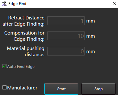
Check Manufacturer and set the following parameters:
Parameter Description Retract distance after edge finding Retract distance after automatic edge finding. Range:-10~1000. Compensation for edge finding Compensation for edge finding range:-10~100. Material pushing distance To avoid no tubes when edge finding. Set the retract distance, that is, before edge finding, the distance of material pushing in the positive direction of the Y axis. After the movement is completed, turn on the follow-up, and the Y axis moves backward to start edge finding.
Range:0~10000.Height of edge finding Range:0.5~10. Click Start, if need stop to click Stop.
Set Tube Size
Set the type and size of the machining tube in the software according to the actual situation.
This chapter takes rectangular tube as an example.
Operating Steps:
In the menu bar, click Common →
 → Tubes to open the Tube Wizard dialog box:
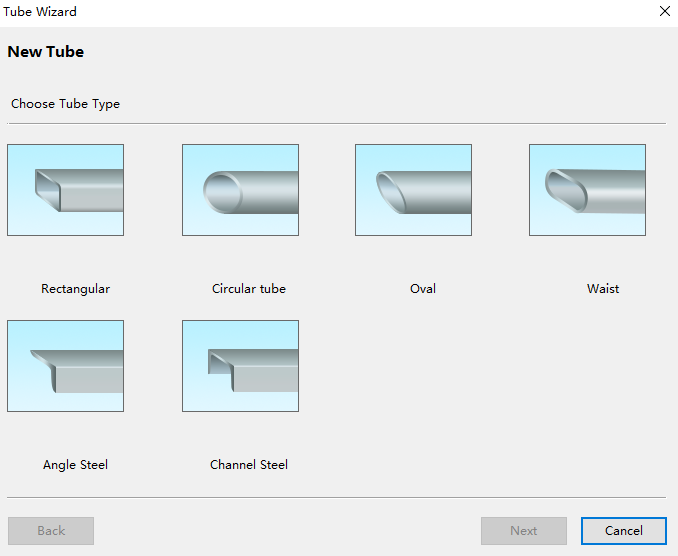
Select Rectangular Tube to set the size of the new tube - rectangular tube:
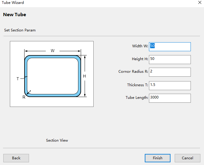
When setting the R corner radius of rectangular tube, it can be about 0.5mm larger than the original radius. Prevent the offset of the tube size from causing poor cutting effect of some edges of the tube.
Click Finish.
Related Task:
To modify the tube size. For details, see Modify Tube Size.
Set Mark Point
It is used to set the mechanical coordinate of the target position as the mechanical coordinate of the marked point, and move the cutting head back to the marked point when necessary.
Operating premise:
Make sure that each axis has returned to the machine origin.
Operating Steps:
In the menu bar, click Common →
 Mark Point to open the Mark Point dialog box:
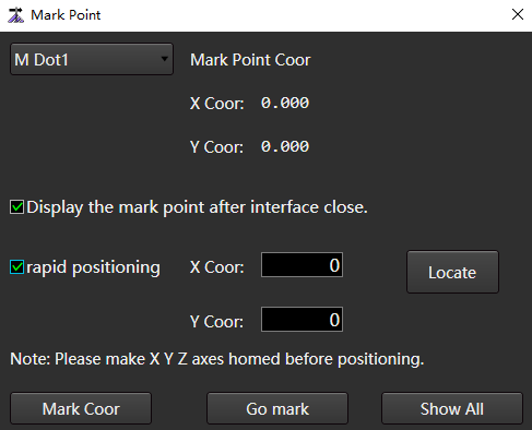
In the machine tool control bar, click the X axis and Y axis direction buttons to move the cutting head to the target position.
Select M Dot n. The value range of n is 1~8.
Click Mark Coor.
After selecting the target position, click Go Mark, and the cutting head will automatically return to the marked point position.
(Optional:) If the target position is not a mark point and it is necessary to quickly locate to the specified mechanical coordinate position, check Rapid Positioning, set the coordinate value and click Locate.
Related Tasks:
In the Mark Point dialog box, you can also perform the following operations:
If you need when to close the mark point dialog box, the drawing area still displays the mark points, check Display the Mark Point after Interface Close.
To display all marked points in the drawing area, click Show All.
Set Common Parameter
Common parameters include machine param, user habit, gas param, burst param, follow-up control, clean by gas, and unit switch.
Operating Steps:
In the menu bar, click Common →
 to open the Common Param dialog box:
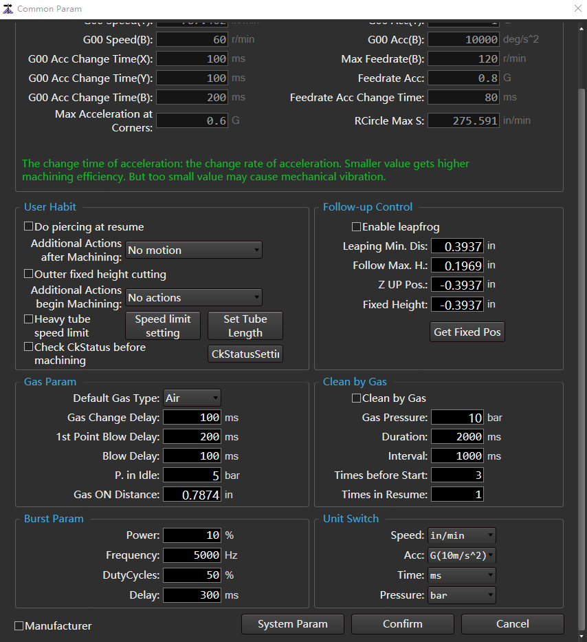
Check Manufacturer to activate Machine Param.
Set Machine Param, and the parameters are described as follows:
Parameter Description G00 speed G00 speed of each axis during machine tool machining.
Range:1~100000.G00 acc change time G00 acceleration change time of each axis during machine tool machining.
Range:1~10000.Max acceleration at corners The maximum acceleration of feeding movement on adjacent axes, and the recommended value is 1~2 times of the acceleration.
Range:0.1~50000.G00 acc The maximum acceleration of each axis during machine tool machining.
Range:0.001~50000.Feedrate acc The total acceleration of the acceleration phase during machine tool machining.
Range:0.1~50000.Feedrate acc change time Change time of uniaxial acceleration during machining. Rcircle max s The maximum allowable speed corresponding to a reference circle with a diameter of 10 mm.
Range:1~1000000.Set User Habit, and the parameters are described as follows:
Parameter Description Do piercing at resume Whether to enable do piercing at resume. Additional actions after machining It includes not move, return to marked point, return to fixed point, return to workpiece origin and other additional behaviors of X and Y axes after machining. Outter fixed height cutting When checked, the outer length is cut using the fixed height action. Additional actions begin machining Includes no operation and automatic clearing of workpiece coordinates. Heavy tube speed After checking, configure the tube heavy speed limit conditions:
Make sure to add and set materials in Manage Material before configuration.
1. Click Speed Limit Setting to open the Heavy Tube Speed Limit dialog box.
2. Enter a value in the Data Array input box and click Confirm.
3. In the Data area. Configure speed limit strategy for different tube weights, acceleration and speed of Y axis and B axis.
Note: Data area, the weight is required to be input in an incremental manner.
4. Click Update.Set tube length When configuring different tube length, it shall be in the chuck clamping position. Click Set Tube Length to open the Set Tube Length dialog box. For the setting method, see Set Tube Length. Check ckstatus before machining If checked, it will be checked whether the status of the front and rear chucks is consistent with that set in Ckstatus Setting before machining. Ckstatus setting Configure the chuck or unclamp action of the front and rear chucks for detection before machining.
1. Click Ckstatus Setting to open the Ckstatus Setting dialog box.
2. Check the chuck to be set, and Check Chucking or Unclamp according to the actual situation.
3. Click Confirm.Set Follow-up Control, and the parameters are described as follows:
Parameter Description Leapfrog Whether to enable leapfrog function. Leaping Min. dis When the distance is less than this value, leapfrog will not be carried out and the cutting head will not be lifted. Directly traverse to the next graphic starting point. Follow Max. H When the cutting height/perforation height is less than this value, it directly follows the set height; When the cutting height/piercing height is greater than this value, follow it to 1mm and then lift it to the set height. Z up Pos. After return to the mechanical origin, close the following or the mechanical coordinate position where the Z axis stop at the end of machining. Fixed height After the fixed height cutting is enabled, the follow-up is not opened during the cutting process, and the Z axis is fixed at a Fixed Height Position.
You can move to the actual height and click Gst Fixed Pos or enter it manually.Set Gas Param, and the parameters are described as follows:
Parameter Description Default gas type Open the default gas used in the blowing port. When the user select oxygen blowing, the proportional valve can open the port. Gas change delay It is mainly used for progressive pierce and staged pierce. If the cutting gas is different from the pierce gas, the laser is not turned off during the gas switching process after the completion of piercing. 1st point blow delay Blowing delay after machining start/breakpoint resume. Blow delay The blowing port is switched from closed state to open state, and the blowing delay will be executed. P. in idle The air pressure value for manual blowing in idle state. Gas on distance The maximum linear distance between two entities switch. Set Clean by Gas, and the parameters are described as follows:
| Parameter | Description |
|---|---|
| Clean by gas | Whether to enable clean by gas function. Clean by gas function is used to blow air before cutting, which is used to clean the nozzle and make the gas more sufficient in the pipeline to ensure the actual cutting quality. |
| Gas pressure | Percentage of air pressure used for gas cleaning. |
| Duration | The duration of gas cleaning. |
| Interval | The time interval between cleaning when the number of clean is greater than 1. |
| Times before start | Number of times the gas was cleaned when the machining was started. |
| Times in resume | The number of times the gas is cleaned when the breakpoint resumes. |
Set Burst Param, and the parameters are described as follows:
Parameter Description Power Set the laser intensity at burst. Frequency The frequency of light emitted by the pulse during burst. Duty cycles The duty cycle corresponding to burst. Delay Duration of laser on during burst. Set Unit Switch, and the parameters are described as follows:
Parameter Description Speed Optional: mm/s、mm/min、m/min Acc Optional: mm/s2、m/min2、G(10m/s2) Time Optional: ms、s Pressure Optional: bar、psi、Mpa (Optional:) If you need to switch to system parameters, click System Param to open the System Parameter dialog box. For details, see System Parameters.
Click Confirm.
Follow-up Control
Overview
The corresponding relationship between capacitance value and distance is used to control the Z axis floating up and down in real time to ensure that the relative distance between the cutting head and the plate is always constant.
In the menu bar, click Common → to open the Follow-up Control page:

- Page Switch Area
- Follow-up Control Area / Follow-up Parameter Setting Area
- Coordinate Display Area
- Manual Control Area
- Follow-up Control Button
Page Switch Area
| Page | Description |
|---|---|
| System page | Enter the follow-up control area. |
| Parameter page | Enter the follow-up parameter setting area. |
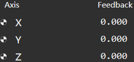
Coordinate Display Area
The mechanical coordinates and workpiece coordinates of each axis are displayed.
Manual Control Area
Manually control the machine tool movement.
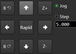
The manual control area includes:
| Control button | Description |
|---|---|
| Axis direction button | Click the direction button corresponding to each axis to control the positive or negative movement of each axis of the machine tool. |
| Continuous rapid mode | ▪ In the continuous low speed mode, click the Rapid button to highlight and switch to the continuous rapid mode. ▪ Press an axis direction button, the machine tool moves at low speed/high speed, and stop after releasing the button. ▪ Press several direction buttons at the same time, the selected axis moves at low speed/high speed at the same time, and it stop at the same time after releasing the button. |
| Step mode | Click the axis direction button, and the machine tool will stop after moving the set step. |
Follow-up Control Button
Control the machine tool to perform follow-up related operations.
| Control button | Description |
|---|---|
 Follow Follow |
The system automatically runs the following function when there is calibration data. Click this button again, and the following will stop and the Z axis will stop automatically following when it returns to the berth position, and the Z axis will stop at the current position. |
 Z Home Z Home |
The Z axis will return to the mechanical origin. Click this button again to stop returning to the mechanical origin. After the execution of returning to the mechanical origin, a  sign will appear in front of the Z axis. sign will appear in front of the Z axis. |
 Stop Stop |
The system will stop the current movement and enter the idle state, which is a method for the system to interrupt the task normally in the follow-up control process. |
 E-stop E-stop |
System emergency stop. |
 Servo Calibration Servo Calibration |
It is a special button under the speed loop control mode. The system automatically performs compensation and clear servo zero drift. |
 Calibration Calibration |
Perform the calibration of the cutting head. Click this button again to stop automatic calibration. |
 One Key Calibration One Key Calibration |
The system will automatically calibrate the cutting head with one key. |
| Perform data clearing, and the software will clear the calibration data and reset the touch part capacitance. |
Follow-up Control Area
Include the following areas:
Main Parameter Area
The parameters displayed in this area are divided into:
- Real time monitoring parameters (values cannot be modified):
| Parameter | Description |
|---|---|
| Enable | After click Follow, the follow enable changes from closed state to open state, and this parameter changes from displaying Close to Open. |
| Z speed | Displays the current Z axis running speed. |
| Z Pos. | Displays the current Z axis mechanical coordinate. |
| Capacitance | Displays the current capacitance value. When the cutting head is closer to the plate, the parameter is smaller; When the cutting head touches the plate, this parameter is 0 (metal plate). |
Part of common follow-up parameters (values can be modified):
Parameter Description Follow height The height of the cutting head when following. Max speed The maximum speed of the cutting head when following. Sensitivity Control the sensitivity of follow-up. Berth pos After returning to the mechanical origin, turn off the following or when the machining is finished, the berth position of the cutting head's mechanical coordinate Click the current value of the parameter and enter the parameter value to be modified in the dialog box. For details, see Parameter.
Oscillographic Area
Click the Calibration Data button in the upper right corner to switch to the following curve page:
Calibration Data
The curve shows the corresponding relationship for the capacitance and position between the cutting head and the plate when the cutting head is automatically calibrated.
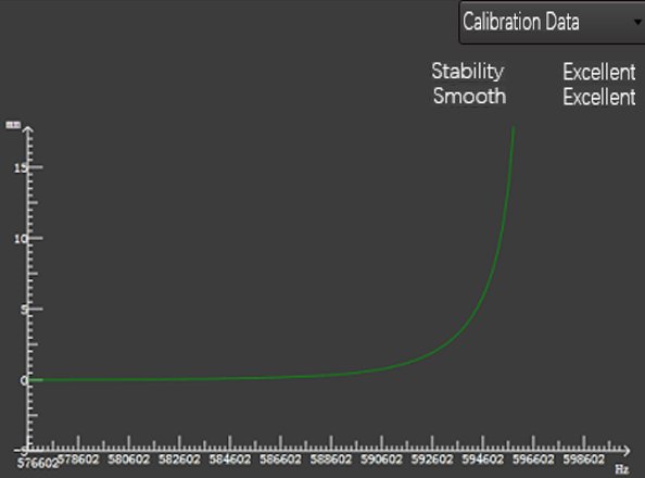
- X axis: Capacitance value.
- Y axis: The distance between the cutting head and the plate.
Real-time Capacitance
The curve shows the real-time capacitance change over a period of time.
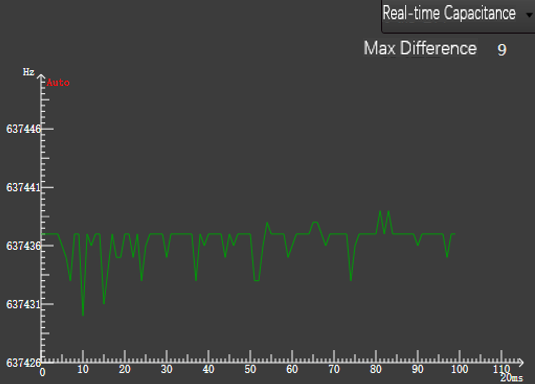
- X axis: Time.
- Y axis: Capacitance value.
While keeping the cutting head and plate stationary, observe the Max Difference in the upper left corner, which reflect the difference between the maximum and minimum capacitance during this period. Because the greater the value is, the greater the interference is, and the more unstable the capacitance measurement is, so Max Difference is not greater than 30 as the ideal value.
Follow Error
The curve shows the difference between the current Follow Height and the set follow parameter Follow Height, reflect the dynamic accuracy of the follow effect.
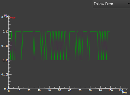
On the Follow Error page, pause the waveform: Double click any point in the page to pause the waveform, and the
 sign at the top of Y axis will become
  .
.
Follow-up Parameter Setting Area
Display all parameters related to servo control. For details, see Parameter.
Based on user permissions and identity, the follow-up parameters are divided into operator parameters and manufacturer parameters, and the system displays operator parameters by default.
Select the following method to open the Parameter Setting dialog box and enter the parameter value to be modified:
After moving the cursor to the current value of the parameter, double click the left mouse button.
Press the direction keys ↑, ↓, ←, → on the keyboard, and then press the Enter key.
To view or modify the manufacturer's parameters, check the manufacturer and enter the password.
Operation
After understanding the layout and application of the follow-up debugging operation interface, start follow-up debugging.
Before the follow-up debugging, do the following operations:
Follow up debugging according to the following steps:
After debugging, Check Follow-up is successfully debugged or not.
Execute Preparatory Project
Operating Steps:
Check that the hardware is installed correctly.
Check that the drive parameters and follow-up Parameter have been set.
Move the Z axis in the positive or negative direction in the step mode, and observe whether the Z axis coordinates change the corresponding step length.
Pay attention to the positive and negative changes. If they are inconsistent, repeat steps 1 to 2.
Check and ensure that there is no alarm in the software, and the Current Capacitance parameter on the interface has a value display.
Make sure that the Z axis direction is adjusted correctly.
Make sure that the System Parameter of the software, the basic movement and coordinate display are correct, and the Z axis can return to the mechanical origin correctly.
Detection Capacitance
Check the status of the capacitance sensor when the cutting head is stationary or running.
Operating Steps:
Contact the plate with the cutting nozzle and ensure that the current capacitance value is 0
Set the follow-up parameter Z axis Berth.
Move the cutting head where the distance between the cutting head and the plate surface is more than 30mm, and keep the cutting head still to ensure that the current capacitance value is stable:
If it is unstable, the current electrical interference is serious. For details, see Serious Electrical Interference.
Execute Servo Calibration
In non-bus control system, servo calibration solves the problem of servo motor zero drift caused by speed loop control.
Operating Steps:
In the manual control area, click the direction button to move the cutting head to the middle of the travel to prevent the cutting head from moving beyond the travel range.
Click
Servo Calibration, and the system will automatically generate the value of servo parameter Servo Compensation Parameter.At this time, the cutting head moves back and forth slightly to compensate.
Execute Automatic Calibration
Acquisition capacitance data matches the correspondence between capacitance and height.
Operating Premise:
- The follow-up parameter Non-metal Calibration has been set to the type of actual calibration material.
- Capacitance detection is 0.
Operating Steps:
Move the cutting head to about 5mm near the plate surface and keep the plate surface still.
Click
Calibration, the system starts to calibrate, and takes about 20s to complete the calibration.(Optional:) If the system needs to calibrate the cutting head automatically, click
One Key Calibration.Note
If it is not calibrated, one key calibration cannot be used.
The automatic calibration process is as follows:
The cutting head slowly moves downward to detect and touch the plate.
After touching the plate, move upward for 5mm.
The cutting head moves down slowly for the second time to detect and touch the plate.
After touching the plate, slowly move up the set calibration distance and acquire the calibration data to obtain the calibration curve:
After calibration, the system automatically estimates the stability and smooth of the calibrated curve:
| Index | Description |
|---|---|
| Stability | It refers to the data difference between falling 5mm to touch the plate and lifting 5mm to touch the plate. The greater the difference, the worse the stability. If the stability is Poor, it may be that the vibration is large or the external interference is strong, and it needs to be recalibrated. |
| Smooth | Refers to the smoothness of the curve. If the smooth is Poor, it means that the curve is not smooth, has undulations or burrs, and needs to be recalibrated. |
Caution
During calibration, pay attention to using the E-stop button in time to prevent damage to the machine tool caused by continuous pressing of the cutting head when the touch part capacitance is incorrect.
Check Follow-up
Operating Premise:
Successfully calibrated.
Operating Steps:
During the Follow-up Control operation, ensure that the cutting head is not oscillated and the following distance is correct.
After that, you can use a screwdriver or a small piece of iron to move back and forth under the cutting head, and observe whether the cutting head move up and down according to the position of the screwdriver or the small piece of iron, and whether the cutting head is ossification.
If oscillation, reduce the positioning sensitivity and increase the inposition tolerance parameter to suppress oscillation.
In the menu bar, click Set →
 to find the system parameter Out Margin Check and set it to Yes.
Enable this feature can effectively improve security.
Draw the tool path, machine without turn on the laser, and observe whether the cutting head is oscillation during the following process.
If oscillation, reduce the positioning sensitivity and increase the inposition tolerance parameter to suppress oscillation.
Parameter
All follow-up parameters and their descriptions on the Parameter page of the Follow-up Control dialog box:
- Setting
- Follow Setting
- Follow-up
- Calibration Setting
- Speed Setting
- Real-time Statue Check
- Manual Speed
Setting
| Parameter | Description | Range | Value |
|---|---|---|---|
| Axis direction | Specifies the direction in which the mechanical coordinate value of the Z axis increases. When manually operating the machine tool, if the axis movement direction is opposite to the direction determined by the Right Hand Rule, modify this parameter. | ▪ 1:Positive direction. ▪ -1:Negative direction. |
1 |
| Pulse equivalent | The displacement or angle generated by each control pulse on the Z axis. | 0.000001mm/p~999mm/p | 0.001mm/p |
| Workbench stroke upper limit (Z) | Upper limit of soft limit value. | -1000mm~99999mm | 0 |
| Workbench stroke lower limit (Z) | Lower limit of soft limit value. | -99999mm~0mm | -1000 |
| Screw pitch (Z) | The screw pitch in the Z axis direction. | 0mm~360mm | 10 |
| Coarse positioning direction (Z) | In the process of returning to the mechanical origin, the motion direction of the Z axis coarse positioning stage. | ▪ 1:Positive direction. ▪ -1:Negative direction. |
1 |
| REF switch positioning speed | In the process of returning to the mechanical origin, the feed speed of the Z axis coarse positioning stage. | 0.1mm/min~10000mm/min | 1800 |
| Retract distance (Z) | The additional travel distance of Z-axis after the end of the fine positioning stage returning to the mechanical origin. A positive value means go back in, a negative value means go out, and a value of 0 means not move. | -100mm~1000mm | 2 |
Follow Setting
| Parameter | Description | Range | Value |
|---|---|---|---|
| Stand-off distance | The relative distance between the cutting head and the plate during follow-up control. | 0mm~30mm | 1 |
| ZUP position | After return to the mechanical origin, turn off the following or the mechanical coordinate where the Z axis berth at the end of machining. | -100mm~100mm | -10 |
| Safe lift height | The safe height for lift when the Z axis does not return to the mechanical origin. | 0mm~100mm | 40 |
| Follow-up to the max height directly | Follow the maximum height directly. | 0.01mm~16mm | 5 |
Follow-up
| Parameter | Description | Range | Value |
|---|---|---|---|
| Positioning sensitivity | Control the sensitivity of follow-up positioning movement. | 1~20 | 8 |
| Follow-up sensitivity | Control the sensitivity of follow-up. | 1~5 | 1 |
| Follow-up feed forward | In order to speed up the following, within a certain range, the larger the value, the faster the response speed. If the feed forward is too large, the follow up will follow the oscillation. | 0~100 | 50 |
| Inposition tolerance | When it is detected that the height is Follow height ± Inposition Tolerance Value, it is considered that the follow-up is in place. | 0mm~655mm | 0.3 |
| Vibration suppressing level | The higher the oscillation suppression level is, the stronger the suppression effect on the occurrence of plate oscillation in the machining process is, and the single follow-up sensitivity will be correspondingly reduced. | 0~5 | 1 |
| Servo compensation parameter | Special parameters in speed loop control mode. The value generated after servo calibration. | -255~255 | 0 |
| Part touching delay (positioning) | Touch part delay during positioning control. | 0ms~20000ms | 300 |
| Part touching delay(follow-up) | Touch part delay during follow-up following status. | 0ms~20000ms | 500 |
| Part touching delay(pierce) | Touch part delay during pierce. | 0ms~20000ms | 600 |
| Enable anti-collision | When it is enabled, the cutting head is automatically lifted up when it is detected that the cutting head may collide during dry running. | ▪ Yes: open ▪ No: close. |
Yes |
| Speed gain | Special parameters in speed loop control mode. The rated power of the motor divided by 10V matches the speed command input gain in the motor. | 10~2000 | 300 |
| Capacitance threshold to trigger cutting head alarm | Threshold value of capacitance to trigger exception alarm in cutting head. | 100Hz~100000Hz | 500 |
| Additional capacitance threshold to trigger cutting head alarm | When the capacitance compensation is turned on, the threshold value of capacity to trigger exception alarm in cutting head will be added with additional detection tolerance. | 100Hz~100000Hz | 1500 |
| Capacitance compensation | Whether capacitance compensation is carried out. | ▪ Yes: open ▪ No: close. |
No |
Calibration Setting
| Parameter | Description | Range | Value |
|---|---|---|---|
| Enable non-metal calibration | Whether non-metal calibration is used. | ▪ Yes: Automatic calibration of metal materials. ▪ No: Automatic calibration of non-metal materials, such as wood, plastic, etc. |
No |
| Touch part capacitance | The capacitance value marked by frequency when touching part. | 0Hz -1000000Hz | 0 |
| Calibration length | During calibration, the capacitance data within this range shall be recorded. When the Z axis travel is short, the parameter value can be appropriately reduced. | 5mm~50mm | 18 |
| Part touching speed | When calibrating, the speed of touch part movement. | 0mm/min~10000000mm/min | 80 |
| Calibrating speed | Calibration speed. | 0mm/min~10000000mm/min | 80 |
| Capacitance fluctuation detection | When the capacitance fluctuation is less than the threshold value every 1mm during calibration, the calibration process is interrupted. | - | 30 |
Speed Setting
| Parameter | Description | Range | Value |
|---|---|---|---|
| Z G00 speed | The speed of downward and upward movement of the floating head. When the dry running speed is set to a large value, the calibration length needs to be increased so that there is enough deceleration area when following the downward direction to avoid collision with the plate. | Maximum speed of 0~axis | 15000 |
| Follow acceleration | Follow the acceleration. | 1000mm/s2~50000mm/s2 | 12000 |
| Axis maximum speed(Z) | The following speed and dry running speed cannot be greater than this speed. | 1mm/min~100000mm/min | 30000 |
| Max speed of Z axis motor | Maximum speed of Z axis motor. | 1000r/min~20000r/min | 6000 |
Real-time Statue Check
| Parameter | Description | Range | Value |
|---|---|---|---|
| Detect out-margin | Whether or not to enable detect out target at any time, and stop moving when it encounters out-margin. | ▪ Yes: Detection ▪ No:No detection. |
Yes |
| Empty leapfrog detection tolerance | Empty leapfrog detection tolerance. | 0mm~225mm | 3 |
Manual Speed
| Parameter | Description | Range | Value |
|---|---|---|---|
| Manual high(Z) | Acceleration of Z axis in manual mode. | 0mm/s2~100000mm/s2 | 5000 |
| Manual low(Z) | The speed of Z axis during high speed operation in manual mode. | 1200mm/min~30000mm/min | 1800 |
| Manual continuous low(Z) | Default speed of Z axis in manual mode. | 0.1mm/min~1800mm/min | 1200 |
Common Problem
Through this section, you can view the problems encountered in the follow-up debugging process and their solutions.
Serious Electrical Interference
Reason
The position of the servo driver affects the electrical interference.
The shielding layer is damaged or wound to the external iron frame.
There is not conductive between pin 4 of M16 three core aviation plug drag chain cable and amplifier.
There is a gap between the amplifier of the follow-up instrument and the machine tool.
Radio frequency cable is damaged.
The machine tool has poor contact with the ground.
Solution
Methods for Physically Eliminating Interference
Make sure that the servo driver, lambda 5E controller and EX33A expansion terminal board are in good contact with the ground.
If the contact is poor, drive the ground pile again.
Ensure that the cable shield is intact.
If not, replace the cable shield.
Ensure that pin 4 of the M16 three core aviation plug drag chain cable is conductive to the amplifier.
If not, replace the cable.
Make sure that the amplifier of the follow-up instrument is in full contact with the machine tool.
If not, polish the veneer with sandpaper to remove the oxide layer before installing the amplifier.
Test whether the radio frequency cable is intact through the multi-meter.
If not, replace the radio frequency cable.
Make sure that the machine tool is in good contact with the ground.
There is a Deviation Between the Set Follow Height and the Actual Follow Height
Reason
The ceramic ring or nozzle was not calibrated when it was replaced, or it was not firmly installed. The capacitance fluctuates greatly during blowing, resulting in a certain deviation of capacitance curve.
Solution
Follow the steps below to troubleshoot the problem:
- Ensure the ceramic ring or nozzle is securely installed.
- Ensure that the capacitance fluctuation is within the set compensation range when blowing.
If the above is normal, recalibrate. For details, see Execute Servo Calibration and Execute Automatic Calibration.
Capacitance Feedback is Normal, Calibration Result is Good, but Cutting Head often Stops Working
Reason
It may be that the external force generated by the gas of the cutting head causes the poor contact between the internal contact of the ceramic ring and the signal port of the cutting head, triggering the touch part alarm, so that the cutting head will stop working when the nozzle has no direct contact with the plate during the cutting process.
Solution
Replace the qualified ceramic ring.
When Cutting Thin Plate, the Cutting Head Oscillation Seriously, which Leads to Deformation of the Cutting Workpiece Contour
Reason
When cutting thin plates, due to the large cutting air pressure, the plate oscillation greatly during the cutting process. Therefore, it is necessary to reduce the parameter Positioning Sensitivity and increase the parameter Inposition Tolerance to suppress oscillation.
Solution
Adjust the parameter Oscillation Suppression.
When Moving Z Axis or Directly Turning On Follow-up, the System Gives an Alarm of "Follow-up Error Status"
Reason
The superposition of the reverse running direction of the Z-axis motor and the Offset Phenomenon caused by external interference.
It is only caused by Offset Phenomenon.
The simple determination method of Offset Phenomenon is as follows:
Switch on the servo.
Open the cutting software to enable the servo, and observe the servo driver display interface.
If the value changes back and forth and the amplitude is relatively large, it indicates that the external electrical interference is relatively large.
Observe that the coupling at the connection between the Z axis motor and the lead screw rotates back and forth slightly.
Solution
Recalibrate. For details, see Execute Servo Calibration and Execute Automatic Calibration.
Error in Encoder Direction or Axis Direction
Reason
Error in encoder direction or axis direction parameter setting.
Solution
Do the following:
Modify the encoder direction and observe whether the alarm is released.
If it is not released, modify the encoder direction to the value before setting, and change the rotation direction of the driver parameter axis.
If the axis direction and encoder direction are both reverse, set the driver parameter axis rotation direction machine encoder to the reverse value.
Follow-up in Place Waiting Timeout
Reason
- The parameter Inposition Tolerance is set too small.
- Calibrate the data difference.
- During machining, it is affected by external slag spraying.
- Follow-up overshoot.
Solution
Do the following:
Check whether the inposition tolerance is set too small.
The recommended value is 0.1.
Recalibrate. For details, see Execute Servo Calibration and Execute Automatic Calibration.
Adjust the cutting technic.
Ensure that the follow-up parameters and servo driver parameters are set correctly.
If not, reset the servo driver parameters.
The Following Error is Too Large
Reason
The following error is greater than the set out margin tolerance value within a time.
Solution
Do the following:
If the error is reported on a flat surface, it may be caused by the follow-up overshoot. Check whether the servo driver gain is too small.
If it is too small, increase the servo driver gain.
If an alarm occurs during climbing, the follow-up sensitivity may be set too small.
When the System is Idle or In the Process of Machining, Turn On the Following Touch Part Alarm
Reason
The capacitance shall not be greater than that of the touch part plate.
Solution
Follow the steps below to troubleshoot the problem:
Ensure that the set value of the bumper plate capacitance is appropriate.
The default value of 0 is recommended.
If follow is on, touch part alarms:
- Ensure that the parameters Pulse Equivalent, Feedback Pulse Number and Speed Gain are correct.
- Make sure that the drive gain is correct.
Touch part alarm during machining:
- Make sure the manual follow is normal.
- Ensure that the capacitance fluctuation range is within 50 when blowing.
If the above is normal, the servo driver gain may be small, and increase the servo driver gain appropriately.
Touch Part Alarm when the System is Static
Reason
The capacitance value when the capacitance is less than or equal to the touch part.
Solution
Follow the steps below to troubleshoot the problem:
Ensure that the body capacitance value and touch part capacitance are correct.
If not, replace the body capacitance value and touch part capacitance.
For SE001 above V1.4, the normal value of the body capacitance is about 650000. The capacitance of SE0001 in V1.4 and below is about 1.3 million.
Use a multi-meter to measure whether the copper core from the nozzle to the cutting head sensor is conductive.
If it is not conductive, it indicates that there is a problem with the cutting head.
Use a multi-meter to measure whether the nozzle is conductive to the RF cable copper core.
If it is not conductive, it indicates that there is a problem with the RF cable. Replace the RF cable.
Measure whether the resistance between terminals 1-2 of SE001 is 4.8~5.3K Ω (the error range is allowed to be ≤ 5%), and whether the resistance between terminals 2-4 is 0 Ω~1 Ω.
If the resistance value is abnormal, SE001 is damaged. Replace SE001.
Measure whether the corresponding pins of M16 three core aviation line are conductive.
If not, replace the cable.
If all the above are normal, replace the EX33A expansion terminal board.
Follow Overshoot
Reason
The servo response cannot follow the command speed.
Solution
Follow the steps below to troubleshoot the problem:
Ensure that the parameters Pulse Equivalent, Speed Gain, Pulses Per Revolution are set correctly.
Increase the servo driver gain.
Ensure that the maximum speed supported by Z axis matches the dry running speed, and the dry running speed of Z axis can be appropriately reduced.
Focus Control
Cutting different tubes requires different focus; In order to ensure the quality of machining, different focal points should be used during piercing and cutting. The Focus Control function is used to automatically adjust the focus during machining.
In the actual machining process, you can click Layer Setting and set the cutting parameter Cutting Focus or piercing parameter Focus in the Layer Setting dialog box to use this function.
Operating Premise:
Make sure that the system parameter Enable Focus Control is set to Yes, and restart the software to make the setting take effect.
Operating Steps:
In the menu bar, click Common →
 to open the Focus Control dialog box:
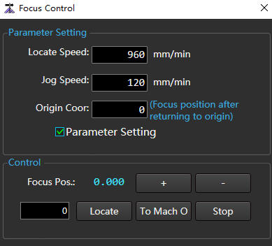
Check Parameter Setting and set corresponding parameters.
Click the following buttons to control the action of the machine tool:
- + / -:Adjust the focus position with Jog Speed.
- Locate: Locate to the focus position set in the left input box at Positioning Speed.
- To Mach O:The W axis returns to the mechanical origin.
- Stop: The W axis stops moving.
Click Confirm.