Other Operations
This section introduces functions and operations. It includes the following:
- Turn on the Spindle in Advance
- Enable Loading/Unloading
- Execute Parameter Related Operations
- Set Offset
- Calibrate the Tool
- Execute Port Related Operations
- Re-connect Terminal Board with Control System ON
- Share Origin Switch Port with Limit Switches Ports
- Enable Tool Guide
Turn on the Spindle in Advance
This operation is used to turn on the spindle of the target cylinder before switching to the target cylinder, so as to reduce the spindle preparation time and improve machining efficiency. It is controlled by the parameter Spindle Pre-start Time.
At present, it is only applicable to the mechanical structure of multi-cylinder-multi-inverter.
To turn on the spindle in advance, do one of the following:
If the system is under Lambda 3S/3L, Lambda 4S, or Lambda 5M configuration, do the following:
Click
 → Technician Interface to switch to technician interface.
Click File → Function Configuration. Function Configuration dialog box pops up.
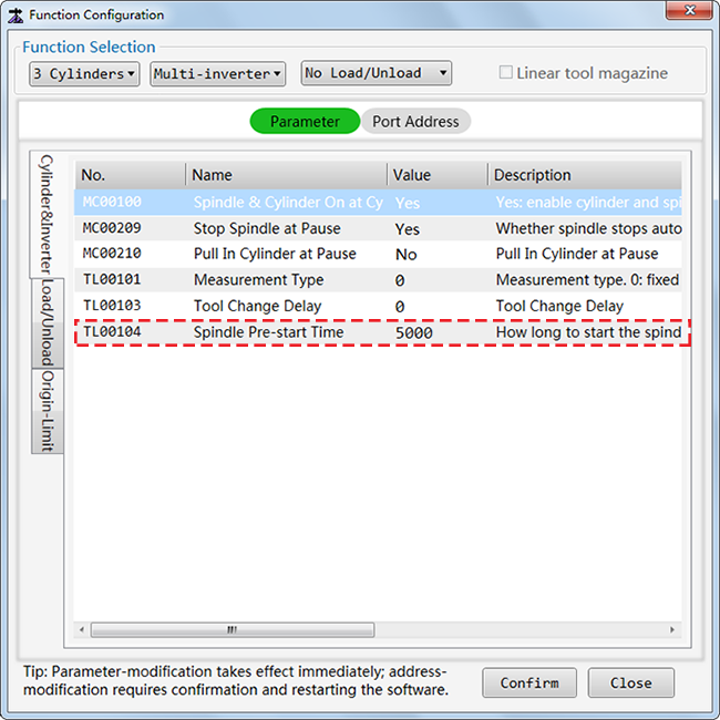
Select functions in Function Selection area and ensure the selected cylinder combination belongs to multi-cylinder-multi-inverter.
Click Parameter → Cylinder/&Inverter, find the parameter Spindle Pre-start Time (Unit: ms) and modify the parameter value based on actual needs.
If the system is under double-station Lambda 4S configuration, do the following:
Click
→ Technician Interface to switch to technician interface.Click System → Global Parameters, select Manufacturer permission and enter the manufacturer password.
Find the parameter Spindle Pre-start Time and modify the parameter value according to actual needs.
See Execute Parameter Related Operations for details.
Example
If the parameter Spindle Pre-start Time is set to 1000 and changing from T1 to T3 for is required. Then:
Before executing T3 command, the system turns on the spindle corresponding to T3 one second in advance.
When executing the T3 command, the system does the following:
- Close the spindle and cylinder corresponding to T1.
- Pull down the cylinder corresponding to T3.
Enable Loading/Unloading
This operation is used to load/unload material.
It is only available to Lamdba 4S configuration and Lamdba 5M configuration.
Thus, before enabling this function, ensure the following:
The used terminal board is Lambda 4S or Lambda 5M.
The software has been switched to Lambda 4S configuration or Lambda 5M configuration.
See Switch System Configuration for how to switch configuration.
- Related parameters and port addresses related to loading and unloading are configured, because the system does not configure the loading and unloading port by default.
If the port address is not set, the related buttons are in gray and the loading and unloading function is disabled.
See Customize Function Configuration for how to configure the function.
To enable loading and unloading material, do one of the following:
Click
 to switch to operator interface and click Load, Unload or Load/Unload in loading and unloading control area. The system automatically executes related operation.
Click
→ Technician Interface to switch to technician interface and do the following:Click File → Function Configuration. Function Configuration dialog box pops up:

Select one of the following in Function Selection area:
- Load: load material.
- Unload: unload material.
- Load/Unload: load and unload material.
Select Load/Unload in the left of parameter list.
Set the following parameters to 1, 2 or 3 in the parameter list:
Load/Unload at Cycle Start : Whether to load or unload material when cycle starts. : 0: none. : 1: load material. : 2: unload material. : 3: load/unload material.
Load/Unload at Cycle Stop : Whether to load or unload material when cycle stops. : 0: none. : 1: load material. : 2: unload material. : 3: load/unload material.
The system automatically loads/unloads material based on the set value.
Click
→ Technician Interface to switch to technician interface and do the following:Click File → Function Configuration. Function Configuration dialog box pops up:
Select Load/unload in the left of the parameter list and check load/unload related codes:
- Load M Code
- Unload M Code
- Load/unload M Code
Do one of the following:
- Click Machine → MDI, enter load/unload related code and execute Start.
- When programming, write load/unload related code into tool path.
Execute Parameter Related Operations
NC60A Multi-process Cutting System provides a wide range of motion control parameters and technic parameters.
To execute parameter related operations, do the following:
Click
→ Technician Interface to switch to technician interface.Do one of the following:
Check and Modify Parameters
To check and modify parameters, do the following:
Click System → Global Parameters. Parameter dialog box pops up:
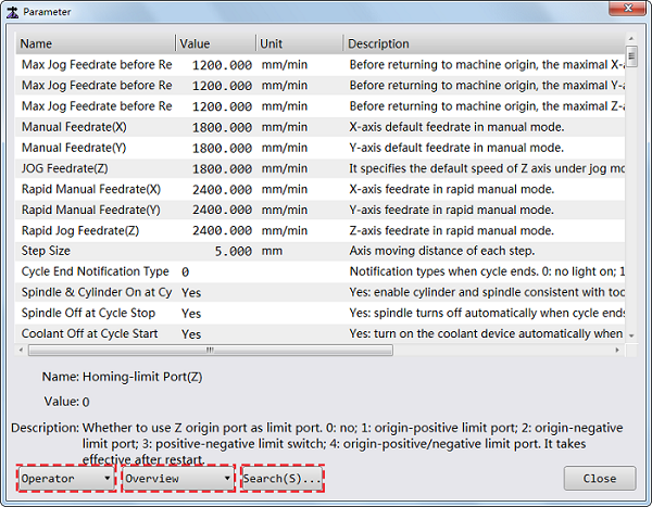
Select access permission:
- Operator: to show parameters under operator permission. It is the default permission.
- Manufacturer: to show parameters under manufacturer permission. Enter the manufacturer password to access these parameters.
Select parameter classification to see related parameters:
- Overview: to show all parameters with operator/manufacturer permission. It is the default classification.
- Axis: to show axis parameters.
- Machining: to show machining parameters.
- Planning: to show planning parameters.
- Compensation: to show compensation parameters.
- Tool: to show tool parameters.
- Others: to show other parameters.
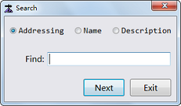
Optional: Click Search to search parameters by:
- Addressing
- Name
- Description
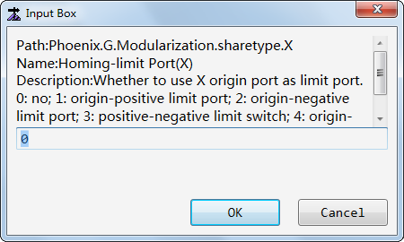
After finding the parameter, double-click the line of the parameter, enter a value and click OK.
If the effective time for the modified parameter is after restart, restart the software after all the parameters have been modified.
Customize Common Parameters
The system supports customizing common parameters, so that you can quickly find and manage frequently used parameters.
To customize common parameters, do the following:
Click
→ Technician Interface to switch to technician interface.Click Common to enter into Common window.
Click Set in the lower right corner. Common Parameters dialog box pops up:
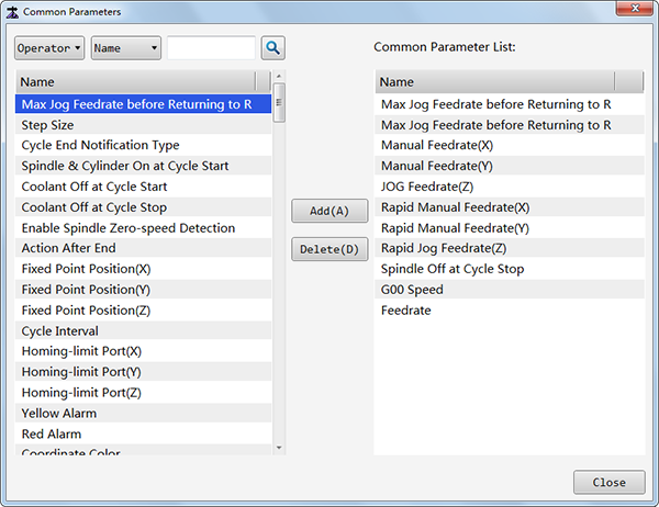
Find the parameter that you would like to add as common parameter by one of the following:
- Permission: Operator and Manufacturer. Operator permission is the default.
- Search: by Name, Description and Addressing. Search by name is the default.
Click Add to add the parameter to the right Common Parameter List.
Repeat step 3 and 4 to add all parameters that you would like to add as common parameters.
Optional: If you need to move a parameter out of the right Common Parameter List, select the parameter on the Common Parameter List and click Delete.
After setting, click Close. The parameters in the Common Parameter List instantly show in Common window.
Back up and Restore Parameter Settings
This operation is used to back up current parameter settings for restoring them later.
Before backing up and restoring parameter settings, ensure parameters have been set correctly.
To back up and restore parameter settings, do the following:
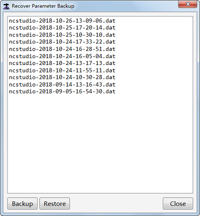
Click System → Recover Parameter Backup. Recover Parameter Backup dialog box pops up:
Do one of the following:
To back up parameter settings, click Backup to start to back up current parameter settings.
The backup file are saved as a DAT file and saved under path Weihong/NcStudio/Config. And the default file name consists of ncstudio and system time.
To restore parameter settings, select a backup file to be restored and click Restore.
Set Offsets
Offset in the system includes the following:
- Workpiece offset: it shows the distance of the workpiece origin relative to the machine origin.
- Public offset: aiming at all WCSs, it is used to adjust workpiece origin of X, Y, and Z-axis.
The relationship among workpiece origin, tool offset and public offset is as follows:
Workpiece Coordinate = Machine Coordinate - Workpiece Offset - Public Offset - Tool Offset
To set offset, do the following:
Click
→ Technician Interface to switch to technician interface.Click Offset to enter into Offset window:
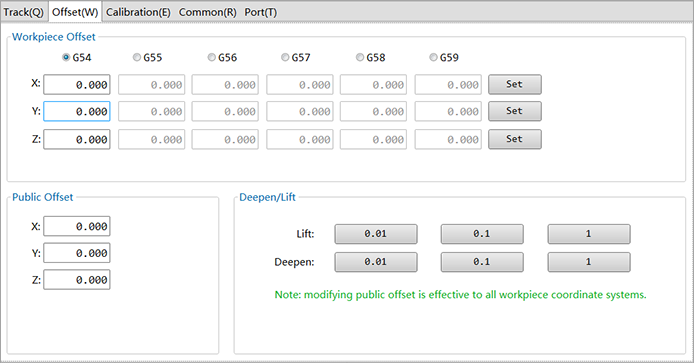
To set the workpiece offset, do the following:
- Select a workpiece coordinate system.
- Click the input box of related axis and set a value.
Click Set to set the current position as workpiece origin.
To set the public offset, do one of the following:
- Click the input box of related axis and set a value.
- Use Deepen/Lift to deepen/lift Z-axis 0.01mm, 0.1mm or 1mm to adjust the public offset of Z-axis.
Calibrate the Tool
This operation introduces how to execute tool calibration through setting parameters that are related to tool calibration.
In terms of permission, it can be divided into the following:
Calibrate the Tool in Operator Interface
To calibrate the tool, do the following:
Switch to Operator interface.
Do one of the following:
To calibrate the current tool, do one of the following:
Click Set T Length to modify Z-axis offset of current tool.
Pull down a cylinder and click Measure to measure length of current tool and set it to tool offset.
To calibrate all tools, click Measure All to measure length of all tools and set it to tool offset.
The system starts calibrating the current tool and then the second tool until it finishes calibrating all tools.
Calibrate the Tool in Technician Interface
To calibrate the tool, do the following:
Click
→ Technician Interface to switch to technician interface.Click Calibration to enter into Calibration window:
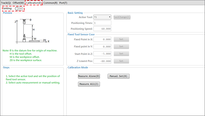
Click on Setting, and enter manufacturer’s password.
All options are available to modification.
In the Basic Setting area, do the following:
- To prepare the spindle tool, select the tool number from the drop-down list, and click Tool Change button.
- To improve tool calibration accuracy, set Fine Positioning Times.
- To improve tool calibration efficiency, set Fine Positioning Speed.
In Fixed Tool Sensor Coor area, set following parameters to define the position of the tool sensor.
- X/Y fixed point
- Z start point
- Z lowest point
Do one of the following:
To measure length of current tool, pull down a cylinder and click Measure Alone. The system automatically executes tool calibration, and saves the result to Z-axis offset for the tool.
To measure length of all tools, click Measure All. The system automatically executes tool calibration, and saves the results to Z-axis for all tools.
To set the current Z-axis machine coordinate to the tool offset of current tool, click Manual Set.
Execute Port Related Operations
By controlling over the input or output ports, you can monitor the status of the machine tool, conduct simulation test and so on.
To execute port related operations, do the following:
Click
→ Technician Interface to switch to technician interface.Click Port to enter into Port window:
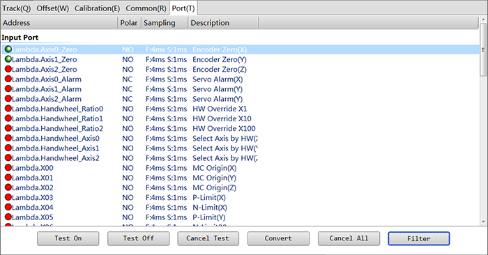
Do one of the following:
- Conduct test: click Test On and Test Off to conduct or close simulation test and click Cancel Test to cancel test.
- Modify port polarity: click Convert to modify port polarity.
- Set sampling: click Filter to set sampling interval and enable/disable filter.
Except these operations, you can also modify and configure port according to the actual usage. See Customize Function Configuration for details.
Re-connect Terminal Board with Control Software ON
When the control system is running and terminal board disconnects with power supply, the control system will prompt with alarm and turn into emergency stop state. With this function, you can re-power on the terminal board and remove alarm, without restarting the software. After that, the software and terminal board can resume good communication.
To use the function, make sure that the terminal board and the software work well before power interruption to the terminal board occurs.
To re-connect the terminal board with control software on, do the following:
- Click → Technician Interface to switch to technician interface.
- Click System → Re-connect Lambda Controller.
Share Origin Switch Port with Limit Switches Ports
This function is used to save IO ports, for example, origin switch port can be used as limit switch port at the same time.
Origin switch port and limit switches ports share in following ways:
- Origin switch port used as positive limit switch port
- Origin switch port used as negative limit switch port
- Positive switch port used as negative limit switch port
- Origin switch port, positive limit switch port and negative limit switch port share the same port
To share the origin switch port and limit switches ports, do the following:
Click
→ Technician Interface to switch to technician interface.To locate parameters Origin-Limit Port, do one of the following:
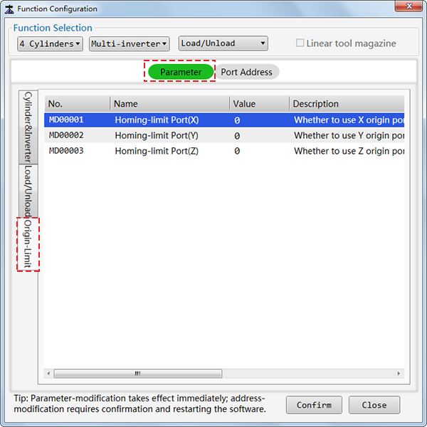
Click File → Function Configuration → Parameter → Origin-Limit:
Click System → Global Parameters, and find parameter in the list:
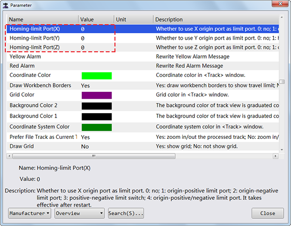
Select the axis, its origin and limit switch and modify their parameter settings:
- N/A (default)
- Share origin port with positive limit switch port
- Share origin port with negative limit switch port
- Share positive and negative limit switch port
- Origin port, positive limit switch and negative limit switch share the same port
Restart the software to validate modifications.
All saved ports are reset to General Output ports.
In case that origin switch, positive limit switch and negative limit switch share the same port, when port signal is triggered, decide which limit switch is working according to the current machine coordinate, as follows:
If current coordinate /< half of travel limit, negative limit switch works.
If current coordinate /> half of travel limit, positive limit switch works.
If current coordinate = half of travel limit, further consider last moving direction, as follows:
- If the axis is moving towards the positive direction, positive limit switch works.
- If the axis is moving towards the negative direction, negative limit switch works.
Enable Tool Guide
Tool Guide function is available only when linear tool magazine is used.
Enable Tool Guide function to do the following:
- Change tool ahead position.
- Change tool upper position.
- Change tool lower position.
- Tool positions in tool magazine.
Before enabling tool guide, make sure Linear tool magazine has been configured. See Customize Function Configuration for details.
To enable Tool Guide function, do the following:
Click
→ Technician Interface to switch to technician interface.Click ToolGuide in Tool Info area. ToolGuide dialog box pops up:
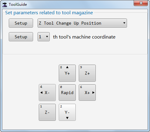
Select the item to be set.
Click axis direction button to manually move the axis to desired position, and click Setup to set current machine coordinate to the item.