Software Interface Overview
NC60A Multi-Process Control System is a CNC system solution for WEIHONG's multi-process cutting machine in woodworking industry. With simple and convenient operation and customized functions, the system can match with different machine models.
According to the operational role and usage scenarios, the system interface can be divided into the following:
-
Used for machining.
It includes frequently used functions in machining for operators.
It is the default interface.
-
Used for debugging the machine tool.
It includes rich functions and machine parameters for technicians.
To switch between two interfaces, do one of the following:
Under operator interface, to switch to the technician interface, click
 → Technician Interface in the upper right corner.
Under technician interface, to switch to the operator interface, do one of the following:
- Click
 in the upper right corner.
 - Click System → Switch to Operator Interface.
- Click
Operator Interface
Operator interface is shown as follows:
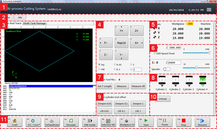
- Title bar
- CNC status bar
- Function windows
- Axis direction and mode selection area
- Axis coordinates display area
- Speed control area
- Tool setting area
- Cylinder control area
- Area for adjusting cylinder tool offset
- Loading and unloading control area
- Operational buttons
Title Bar
This bar consists of the following:
Name of the control system
Current date and time
Burger button
Used to do the following:
- Execute homing.
- Check tool parameters.
- Switch to technician interface.
CNC Status Bar
This bar shows current system mode and status, and prompt or alarm message.
Click the blank area. Log dialog box pops up:
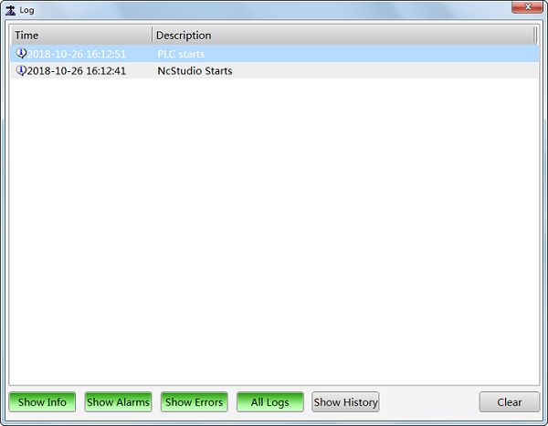
In the dialog box, you can check different types of system logs that are good for troubleshooting.
Function Windows
Function windows include the following:
Ncfile and Trace window
In this window, you can see the following:
- Tool path in real-time during machining or simulation so as to ensure the proper implementation of program file.
- Related program file in details.
Multi-Task Manage window
In this window, you can manage machining tasks and check information of each task.
Axis Direction and Mode Selection Area
This area consists of the following:
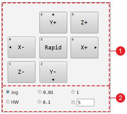
Axis direction buttons:
Used to move each axis towards positive or negative direction:
- Press X- / X+ / Y- / Y+ / Z- / Z+. The machine moves at jogging speed.
- Press Rapid and X- / X+ / Y- / Y+ / Z- / Z+. The machine moves at rapid jogging speed.
Mode buttons:
Used to switch to the following modes:
Jog
Press an axis direction button. The machine keeps running until you release the button.
HW
The machine is controlled by the handwheel.
Step
Click an axis direction button. The machine moves 0.01 mm(inch), 0.1 mm(inch), 1 mm(inch) or customized step size.
The default customized step size is 5mm(inch) and the value should not be too large to avoid damage due to misoperation.
Note: Please do not click axis direction button too frequently because the system needs a certain time to execute the command.
Axis Coordinates Display Area
This area consists of the following:
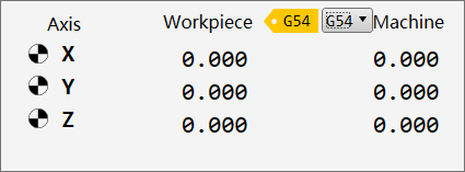
Workpiece coordinates
Machine coordinates
After returning to the machine origin, sign
 appears before each axis.
Speed Control Area
This area consists of the following:
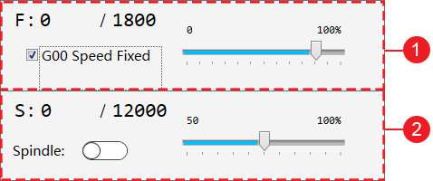
Feed setting area
Used to do the following:
- Set feedrate override.
- Modify setting speed.
- Check actual speed.
Relationship among them is as follows:
Actual Speed = Setting Speed * Current Feedrate OverrideSpindle setting area
Used to do the following:
- Set spindle override.
- Modify spindle setting speed.
- Check actual spindle speed.
Relationship among them is as follows:
Actual Spindle Speed = Setting Spindle Speed * Current Spindle Override
Tool Setting Area
In this area, you can check the current tool and do the following:
Click Set T Length to modify Z-axis offset of current tool.
Click Measure to measure length of current tool and set it to tool offset.
Click Measure All to measure length of all tools and set it to tool offset.
Cylinder Control Area
In this area, you can control cylinders by clicking related cylinder to enable it.
The number of cylinder differs according to the cylinder selection in Function Configuration dialog box.
If no cylinder is selected in the dialog box, this area will be hidden.
See Customize Function Configuration for details of function configuration.
Area for Adjusting Cylinder Tool Offset
In this area, you can adjust cylinder tool offset.
If no cylinder is selected in Function Configuration dialog box, this area will be hidden.
See Customize Function Configuration for details of function configuration.
Loading and Unloading Control Area
In this area, you can enable loading and unloading by clicking related buttons.
The area differs according to the selection of loading or unloading in Function Configuration dialog box.
If loading or unloading is not selected in the dialog box, this area will be hidden.
See Customize Function Configuration for details of function configuration.
Operational Buttons
These buttons are used to execute corresponding operation:
![]()
: Used to load a program file.
![]()
: Used to clear a single axis or all axes.
![]()
: Used to return to the set position of the fixed point.
![]()
: Used to execute simulation to check the tool path in Ncfile and Trace window in real-time.
![]() : Used to enable handwheel to control the machine tool.
: Used to enable handwheel to control the machine tool.
![]()
: Used to select related lines of the program file to be machined.
![]()
: Used to return to the workpiece origin.
![]()
: Used to start machining.
![]()
: Used to pause machining.
![]()
: Used to stop machining.
![]()
: Used to resume machining from the exact interrupted position when power interruption or e-stop occurs and the workpiece origin is secured.
Technician Interface
The interface diagram is as follows:
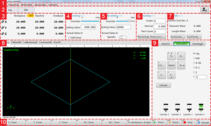
- Menu bar
- CNC status bar
- Axis coordinates display area
- Feed setting area
- Spindle setting area
- Cycle setting area
- Tool information
- Function windows
- Mode control bar
- Operational buttons
CNC Status Bar
This bar shows the following:
- Current system mode
- Current system status
- Prompt or alarm message
- Manufacturer permission button
Click the blank area. Log dialog box pops up:
In the dialog box, you can check different types of system logs that are good for troubleshooting.
Axis Coordinates Display Area
This area consists of the following:
Workpiece coordinates
Machine coordinates
After returning to the machine origin, sign
appears before each axis.
Feed Setting Area
In this area, you can do the following:
- Set feedrate override.
- Modify setting speed.
- Check actual speed.
Relationship among them is as follows:
Actual Speed = Setting Speed * Current Feedrate Override
Spindle Setting Area
In this area, you can do the following:
- Set spindle override.
- Modify spindle setting speed.
- Check actual spindle speed.
Relationship among them is as follows:
Actual Spindle Speed = Setting Spindle Speed * Current Spindle Override
Cycle Setting Area
In this area, you can do the following:
- Set cycle time.
- Set cycle interval.
- Reset workpiece count.
- Check machining statistics.
Tool Information
In this area, you can do the following:
- Check current tool number.
- Check diameter wear of current tool.
- Check length wear of current tool.
- Open ToolGuide dialog box and set parameters related to tool magazine.
- Set tool compensation parameters.
Function Windows
Function windows include the following:
Track window:
In this window, you can see the following:
- Tool path in real-time during machining or simulation so as to ensure the proper implementation of program file.
- Related program file in details.
Offset window
In this window, you can set the following:
- Workpiece offset
- Public offset
Calibration window
In this window, you can do the following:
- Change the active tool and its related parameters.
- Set the position of fixed tool sensor.
- Select tool calibration mode.
Common window
In this window, you can do the following:
- Check common parameters.
- Modify values of common parameters.
- Customize common parameters.
Port window
In this window, you can do the following:
- Check port polarity
- Conduct test.
- Modify port polarity.
- Set filter.
Mode Control Bar
It includes the following modes:
Auto
Under this mode, it shows the loaded program file in details.
Manual
Under this mode, it shows the following:
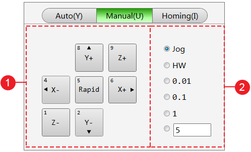
Axis direction buttons
Used to move each axis towards positive or negative direction:
- Press X- / X+ / Y- / Y+ / Z- / Z+. The machine moves at jogging speed.
- Press Rapid and X- / X+ / Y- / Y+ / Z- / Z+. The machine moves at rapid jogging speed.
Mode selection buttons
Used to switch to the following modes:
Jog
Press an axis direction button. The machine keeps running until you release the button.
HW
The machine is controlled by the handwheel.
Step
Click an axis direction button. The machine moves 0.01 mm(inch), 0.1 mm(inch), 1 mm(inch) or customized step size.
The default customized step size is 5mm(inch) and the value should not be too large to avoid damage due to misoperation.
Note: Please do not click frequently for the system needs a certain time to execute the command.
Homing
Under this mode, it includes the following operations related to homing (returning to the machine origin):
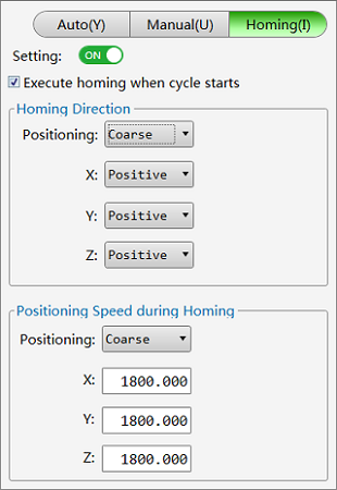
- Setting homing direction
- Setting positioning speed during homing
Operational Buttons
It shows the related operations under different modes.