System overview
NK105 Integrated CNC System (Hereinafter referred to as NK105) is an integrated CNC system with three or four axes, based on embedded industrial control platform and independently developed by Weihong Company.
According to axes, NK105 has the following types:
- General NK105 with three axes: Including X-axis, Y-axis and Z-axis.
- General NK105 with four axes: Including X-axis, Y-axis, Z-axis and A-axis.
- General NK105 with double Z axes: Including X-axis, Y-axis, Z1-axis and Z2-axis.
Hardware
NK105 (E) control box with four axes / NK105 control box with three axes
The two control boxes are almost the same, except the former supports A-axis or Z2-axis.
This manual takes NK105(E) control box with four axes as an example.
Software
About the main interface of NK105, see Main Software Interface for details.
NK105 (E) Control Box with Four Axes
This section introduces the schematic diagram and dimension drawing of NK105 (E) control box with four axes.
This control box, an integration of the system control card, terminal board and other parts, connects to the handheld box with 15-core connecting cable. And the up and down ends at its back are for terminals and the left side is for the USB interface and DB15 interface.
Schematic Diagram
This schematic diagram of NK105 (E) control box with four axes is as follows:
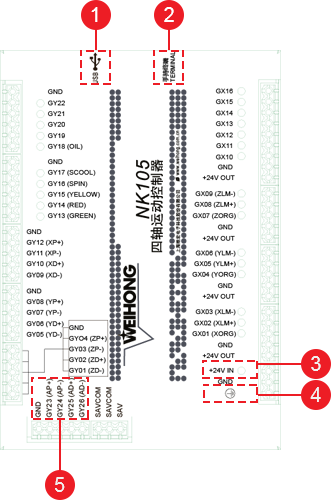
USB interface
It allows NK105 to communicate with other devices.
DB15 interface
It is used to connect to a handheld box.
+24V IN input interface
It is used to connect to a 24V DC power supply.
GND
It is used to connect to the port GND or COM of a DC power supply.
A-axis differential signals
About terminal definition of the control box, see Terminal Definition for details.
Note: It is only applicable to NK105 (E) control box with four axes.
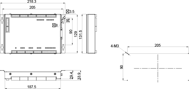
Dimension Drawing (Unit: mm)
The thickness of NK105 (E) control box with four axes is 218.3mm.
The dimension drawing is as follows:
NK105G3 Handheld Box
This section introduces the button definitions on NK105G3 handheld box and dimension drawing of the handheld box.
The handheld box is connected to the control box with a connecting cable, jointly controlling a machine tool. So the moving distance of the handheld box and control box is limited by the connecting cable.
Note: This handheld box is updating. And you can check the newest usage of a single button and button combinations in Help Information interface by pressing
+
.
Button Definition
The definitions of buttons on NK105G3 handheld box are as follows:
A single button
 : It is used to start machining.
 : It is used to pause machining.
 : It is used to stop machining.
 : Arrow button (up).
 : Arrow button (down).
 : Arrow button (left).
 : Arrow button (right).
 : It is used to enable / disable the spindle.
 : It is used to enter the menu interface, or enter the interface for updating the system image at the time of starting NK105.
 : It is used to exit the current interface or dialog box, or return to the previous interface.
 : It is used to clear the workpiece coordinates of X-axis and Y-axis at the same time.
 :
:General NK105 with four axes: It is used to clear the workpiece coordinate of Z-axis or A-axis.
General NK105 with double Z axes: It is used to clear the workpiece coordinate of Z1-axis.
 : It is an auxiliary key or used to switch between Jog and Step mode in the main interface.
 : It is used to increase the feedrate override.
 : It is used to decrease the feedrate override.
 : It is used to move X-axis / Y-axis to the workpiece origin or input the figure 0.
 : It is used to move X-axis in the negative direction or input the figure 4.
 : It is used to move X-axis in the positive direction or input the figure 6.
 : It is used to move Y-axis in the positive direction or input the figure 8.
 : It is used to move Y-axis in the negative direction or input the figure 2.
 :
:General NK105 with four axes: It is used to move Z-axis in the positive direction or input the figure 9.
General NK105 with double Z axes: It is used to move Z1-axis in the positive direction or input the figure 9.
 :
:General NK105 with four axes: It is used to move Z-axis in the negative direction or input the figure 3.
General NK105 with double Z axes: It is used to move Z1-axis in the negative direction or input the figure 3.
 : It is used to switch between high-speed jog mode and slow jog mode or input the figure 5.
 :
:General NK105 with four axes: It is used to move A-axis in the positive direction or input the figure 7.
General NK105 with double Z axes: It is used to move Z2-axis in the positive direction or input the figure 7.
 :
:General NK105 with four axes: It is used to move A-axis in the negative direction or input the figure 1.
General NK105 with double Z axes: It is used to move Z2-axis in the negative direction or input the figure 1.
Button combination
 +
+  : Breakpoint resume.
 +
+  : It is used to show help information.
 +
+  : It is used to clear the workpiece coordinate of X-axis.
 +
+  :
:General NK105 with four axes: It is used to clear the workpiece coordinate of Y-axis.
General NK105 with double Z axes: It is used to clear the workpiece coordinate of Z2-axis.
 +
+  : It is used to increase the spindle override.
 +
+  : It is used to decrease the spindle override.
 +
+  : It is used to move X-axis or Y-axis to the fixed point.
 +
+  : It is used to select the workpiece coordinate system (WCS) from G59 to G54.
 +
+  : It is used to select the WCS from G54 to G59.
 +
+  : It is used to do centering for X-axis.
 +
+  : It is used to do centering for Y-axis.
 +
+  : It is used to return to the machine origin (ie. the origin of the machine coordinate system (MCS)).
 +
+  : It is used to switch between workpiece coordinates and machine coordinates .
 +
+  : It is used to calibrate tool.
 +
+  : It is used to make the fine adjustment.
Button combination (Exclusive to General NK105 with double Z axes)
 +
+  : It is used to clear the workpiece coordinate of Y-axis.
 +
+  : It is used to activate axes.
 +
+  : It is used to switch between Alternative and Linkage mode. See Select the Axis Mode for details.
 +
+  : It is used to set the tool length of Z1-axis.
 +
+  : It is used to set the tool length of Z2-axis.
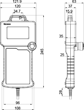
Dimension Drawing (Unit: mm)
The dimension drawing of NK105G3 handheld box is as follows:
Main Software Interface
The main software interface differs in axes. General NK105 with four axes and that with three axes are the same, except the axis number, so their main interfaces are similar. Therefore, this manual does not introduce the main interface of general NK105 with three axes.
General NK105 with Four Axes
When general NK105 with four axes starts, the system automatically enters the machining interface in the manual mode (ie. Jog or Step mode).
The main interface is as follows:
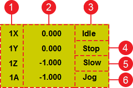
Activated axes
The figures refer to the selected WCS. Specifically, 1 / 2/ 3/ 4/ 5/ 6 respectively refers to G54/ G55/ G56/ G57/ G58/ G59.
Coordinates
Operation status
- Idle: Default status.
- Running
- Pause
- Stop
- Locked: NK105 is locked when the soft limit is triggered.
Spindle status
- Enabled
- Disabled
Speed mode
- High-speed jog
- Slow jog mode
Motion mode
- Jog: Finely adjust the machine coordinate.
- Step: Coarsely adjust the machine coordinate.
General NK105 with Double Z Axes
The main interface is as follows:
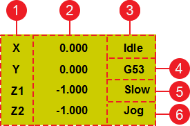
Activated axes
Coordinates
Operation status
- Idle: Default status.
- Running
- Pause
- Stop
- Locked: NK105 is locked when the soft limit is triggered.
Spindle status and coordinate system
Spindle status
- Enabled
- Disabled
Coordinate system
When the coordinate system turns to show the MCS, this area shows G53; when it turns to the WCS, this area shows G54 (default one) / G55 / G56 / G57 / G58 / G59.
Speed mode
- High-speed jog
- Slow jog mode
Motion mode
- Jog: Finely adjust the machine coordinate.
- Step: Coarsely adjust the machine coordinate.