Quick Start
Through this section, you can quick know the machining procedure of NK105, and then start machining.
To start machining, do the following:
- Execute returning to the machine origin.
- Load a program file.
- Select a WCS.
- Define the workpiece origin.
- Set the tool number. (General NK105 with double Z axes)
- Execute fixed calibration. (General NK105 with double Z axes)
- Start machining.
- Adjust machining.
Execute Returning to the Machine Origin
If returning to the machine origin fails due to the origin fault, set the parameter Back REF First to No. See Returning to the Machine Origin before Machining for details.
To execute returning to the machine origin, do the following:
To enter the menu interface, press
 .
.To enter the operation interface, select 3. Operations by pressing
 /
/  , and press
  .
.To enter the axis interface, select 1. Back REF Point by pressing
/ , and press :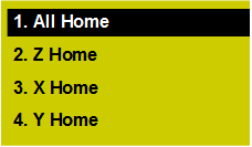
Select the target axis by pressing
/ , and press .Note: For safety, it is recommended to return Z-axis first, or the prompt Dangerous operation, you'd better home Z first. Continue? appears.
Load a Program File
This operation is used to load a program file in the host or a USB flash disk for machining. The supported file format includes NC, ENG, DXF, PLT, TAP and TXT.
Taking loading a program file in a USB flash disk as an example, to load the program file, do the following:
To enter the menu interface, press
.To enter the file interface, select 2. USB Files by pressing
/ , and press :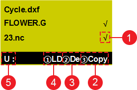
It means the current file is selected.
Copy the selected file.
Delete the selected file.
Load the selected file.
The current disk is a USB flash disk.
Select the target program file by pressing
/ , and press .To load the target program file, press
 .
.
You can also do one of the following for the selected program file in the host or a USB flash disk:
To delete the program file, press
 .
.To copy the program file to a USB flash disk or the host, press
 .
.
Select a WCS
In programming, programmers select a certain given point on workpiece as origin (called program origin or workpiece origin) to establish a new WCS.
In general N105 with four axes, the figures (1 ~ 6) before each axis in the main interface indicate the corresponding WCS (G54 ~ G59).
To select a WCS, do the following:
To enter the menu interface, press
.To enter the operation interface, select 3. Operations by pressing
/ , and press .To enter the interface for selecting a WCS, select 6. Select WCS by pressing
/ , and press :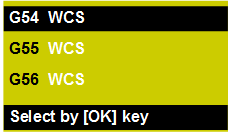
Select the target WCS by pressing
/ , and press .
Define the Workpiece Origin
The workpiece origin is the origin of all axes in the program file. This operation is used to define the workpiece origin according to the actual position and do clearing before machining.
This operation differs in the types of NK105:
General NK105 with Four Axes
To define the workpiece origin, do the following:
To specify the workpiece origins of X-axis and Y-axis, do one of the following:
To clear the coordinates of X-axis and Y-axis at the same time, manually move X-axis and Y-axis to the target position and press
 .
.To separately clear the coordinate of X-axis or Y-axis, do one of the following:
To clear the coordinate of X-axis, manually move X-axis to the target position and press
 + .
+ .To clear the coordinate of Y-axis, manually move Y-axis to the target position and
+  .
.
To specify the workpiece origin of Z-axis, do the following:
To clear the coordinate of Z-axis, manually move Z-axis to the target position and press
.To execute tool calibration, press
+  . After calibration, the coordinate of Z-axis is the workpiece origin of Z-axis.
To specify the workpiece origin of A-axis, manually move A-axis to the target position and press
.
General NK105 with Double Z Axes
To define the workpiece origin, do the following:
To specify the workpiece origins of X-axis and Y-axis, do one of the following:
To clear the coordinates of X-axis and Y-axis at the same time, manually move X-axis and Y-axis to the target position and press
.To separately clear the coordinate of X-axis or Y-axis, do one of the following:
To clear the coordinate of X-axis, manually move X-axis to the target position and press
+ .To clear the coordinate of Y-axis, manually move Y-axis to the target position and press
+ .
To specify the workpiece origin of Z1-axis, manually move Z1-axis to the target position and press
.To specify the workpiece origin of Z2-axis, manually move Z2-axis to the target position and press
+ .Execute fixed calibration for Z1-axis and Z2-axis in turn. After calibration, the coordinates of Z1-axis and Z2-axis are the workpiece origins of Z1-axis and Z2-axis.
About fixed calibration, see Execute Fixed Calibration for details.
Set the Tool Number
This operation is applicable to general NK105 with double Z axes. And it is used to set the same tool number for Z1-axis and Z2-axis.
To set the tool number, do the following:
To enter the menu interface, press
.To enter the operation interface, select 3. Operations by pressing
/ , and press .To enter the interface for setting tool number, select 10. ToolNo Set by pressing
/ , and press .Select the target axis by pressing
/ , input the tool number with the handheld box and press .
After setting the tool number, in the idle / running status, to check the tool number, press  / in the main interface.
Execute Fixed Calibration
This operation is applicable to general NK105 with double Z axes. And it is used to measure the tool on a certain fixed position of the machine tool to reconfirm tool offset. It helps to avoid tool length and the clamping position vary during machining due to tool damage or other causes.
About tool offset parameters, see Tool Change for details.
You can use the same tool sensor to execute calibration for Z1-axis and Z2-axis in turn.
Before executing fixed calibration, set the tool number.
To execute fixed calibration, do the following:
To respectively set the tool length for Z1-axis and Z2-axis, press
+  / + . The prompt Set tool length of Z1-axis / Z2-axis, continue? appears.
Press
. The prompt Succeeded in setting tool length of Z1-axis / Z2-axis. appears.Press
for confirmation.To reconfirm tool offset, press
+ .
Start Machining
This operation is used to start to machine the program file.
During machining, to check the current loaded program file, machining time and machining line, press in the main interface:

To start machining, press  .
.
Adjust Machining
During machining, do one of the following according to your need:
- Adjust the feedrate override.
- Adjust the spindle speed.
- Execute the fine adjustment.
- Handle the soft limit.
- Handle the hard limit.
Adjust the Feedrate Override
You can adjust the actual feedrate by the feedrate override. This operation is used to adjust the feedrate override within 0% ~ 120%.
Every time you press related buttons to adjust the feedrate override, the feedrate override increases / decreases 10%.
To adjust the feedrate override, press  /
/  .
.
Adjust the Spindle Speed
The spindle speed has 11 gears with the minimum unit 0.1. This operation is used to adjust the spindle speed within 0.5S ~ 1.5S.
To adjust the spindle speed, press + / + .
Execute the Fine Adjustment
This operation is used to manually make the fine adjustment in running status or pause status, if the machining is incomplete.
If you temporarily add compensations during machining, it takes effect only in Auto mode.
During executing the fine adjustment, the system automatically enters Step mode. Every time you press an axis button, the corresponding axis moves a step size.
Before executing the fine adjustment, do one of the following:
To enter the running status, start machining.
To enter the pause status after starting machining, press
 .
.
To execute the fine adjustment, do the following:
To enter the interface of fine adjustment, press
+ .To set the step size, press
+ .Step size: 0.01, 0.02, 0.05, 0.10, 0.20, 0.50, 1.00.
To make the fine adjustment for the corresponding axis, press
/  / /
/ /  / / / /
  .
.To return to the main interface, press
 .
.According to the operation status, do one of the following:
Running status: Keep machining.
Pause status: To continue machining from the pause position, press
.
If machining normally ends or if you start machining after pausing it, the fine adjustment is always valid.
If one of the following occurs, the file adjustment is invalid:
If the system enters the idle status.
If you execute breakpoint resume or start machining whether or not the action that you power on after powering off occurs, after machining stops.
If you execute returning to the machine origin again and then start machining, after E-stop or limit alarm occurs.
Handle the Soft Limit
If an axis exceeds the upper / lower limit of workbench travel during machining, the soft limit will be triggered.
To handle the soft limit, do the following:
To exit the alarm dialog box and return to the main interface, press
/ .To release the soft limit, manually move the limit axis in the reverse direction.
After releasing the soft limit, the system forbids the limit axis to move towards the limit direction.
Handle the Hard Limit
The system regularly checks the hard limit, a limit switch (travel switch). And when the hard limit is triggered, the prompt Limit. Exit manually. appears.
To handle the hard limit, do the following:
To release the limit, press
. The system automatically enters Jog mode, and character Limit Rls shows in the lower right corner of main interface:
Move the machine tool away from the limit position. Character Limit Rls turns to Jog.