Wiring
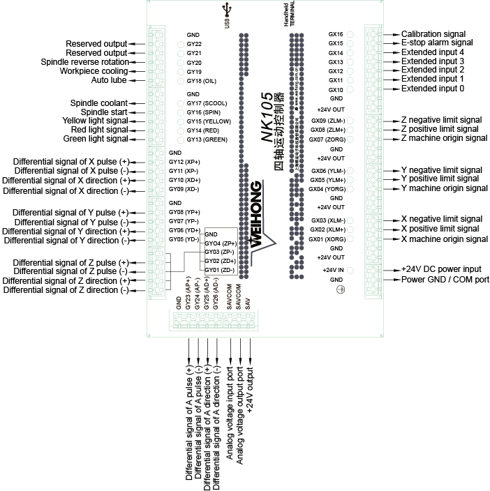
Through this section, you can quick know the supported signal types and terminal definition of NK105 (E) control box with four axes, which can help you finish wiring.
Signal Type
The signal types include the following:
Binary Input Signal
The wiring diagram of the binary input terminal connected to the following switches is as follows:
Mechanical switch
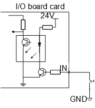
Photoelectric switch or proximity switch
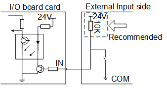
When the binary input terminal is connected to 24V, the input signal is active low:
- For a normal open switch, conducting to GND means the input signal can be received .
- For a normal close switch, disconnecting with GND means the input signal can be received.
Open Collector Output Signal
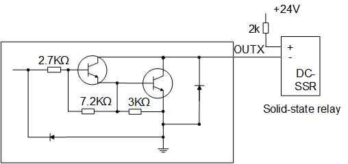
The output port of NK105 (E) control box with four axes belongs to open controller output, with the maximum output current 50mA.
The wiring diagram of the output port connected to a solid-state relay is as follows:
Analog Output Signal
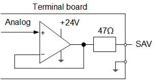
SAV, an output port for 0V ~ 10V controllable voltage, is connected to the input port for analog voltage frequency of the inverter. Therefore, you can control the inverter frequency by changing the controllable voltage, so as to control the spindle speed.
The schematic diagram is as follows:
Differential Output Signal
Differential output signal refers to two equivalent signals with opposite phases from the drive side. You can judge if the logic state of differential signals is 0 or 1 by the voltage difference of these two signals.
The format of pulse commands that control drive motion is pulse + direction, negative logic.
Terminal Definition
The terminal definition of NK105 (E) control box with four axes is as follows:
