Quick Start
Through this section, you can quickly know the following machining processes for NK300CX:
- Load a program file.
- Execute tool calibration.
- Adjust the WCS.
- Define the workpiece origin.
- Select tools for machining.
- Execute selective machining.
- Execute machining.
Load a Program File
This operation is used to load a program file in the host, in a USB flash disk, or from the internet for machining.
To load a program file, do the following:
Press
 , and enter into Program functional area.
Select a type of program file:
Load a Program file in the Host or a USB Flash Disk
This operation is used to load program files or folders in the root directory of the host D:\NcFiles or a USB flash disk, including hidden files and folders.
Taking loading a program file in a USB flash disk as an example, to load a program file, do the following:
To enter into USB interface, press 2:

To select a file path, press H.
To select the target program file, press ↑ / ↓.
Optional: To enable rectangular array or mirroring and duplicating, press F4, and press one of the following:
- F1: set row number, column number, row spacing and column spacing, and generate an array file by pressing F7.
- F2: select the mirroring direction, set position offset, and generate a mirroring and duplicating file by pressing F7.
The generated file shows in the USB interface.
To load the target program file, press F1.
You can also do the following for a program file in the host or a USB flash disk:
- F2: edit the target program file.
- F3: delete the target program file.
- F5: unload the loaded program file.
- F6: create a program file.
- F7: rename the target program file.
- F8: copy the target program file into NK300CX.
Load a Program File from the Internet
This operation is used to establish network connection between NK300CX and PC, to realize two-way transmission between them.
To load a program file form the internet, fo the following:
Set the IP Address
This operation is used to establish the network connection channel between NK300CX and PC by automatically obtaining or manually setting the IP address.
It is default to automatically obtain the IP address. And this operation takes manually setting the IP address as an example.
Before setting the IP address, ensure that NK300CX and PC are in the same subnet.
To set the IP address, do the following:
Press
 → 2 → F1. Network Setting dialog box pops up:
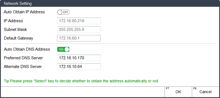
To turn off obtaining the IP address automatically, press
 .
.Press ↑ or ↓ to select the target input box, and set the following addresses:
- IP address: 192.168.1.188 (the first three digits should be the same with that of PC, and the last digit should be different from that of PC)
- Subnet mask: 255.255.255.0 (the same with PC)
- Default gateway: 192.168.1.1 (the same with PC)
To close Network Setting dialog box and save the settings, press F7.
The new networking information shows in Network Connection Status area in Computer interface.
Verify the Connection
This operation is used to verify whether the IP addresses are set successfully by ping command after the IP addresses of NK300CX and PC are set well.
To verify the connection, do the following:
To open the command window, press Win and R keys on the keyboard of PC, and input cmd in Run dialog box.
Input ping and IP address of NK300CX.
e.g. ping 172.16.60.172。Press Enter, and check the result:
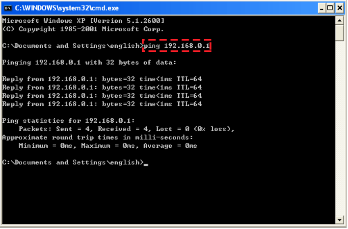
Connection succeeds, and network connection between NK300CX and PC is established.
If connection fails, troubleshoot the following:
Check the corresponding cable interface of the router.
Check the physical connection and IP setting.
See Set the IP Address for details.
Access a Shared Program File
This operation is used to access a shared program file from PC or other integrated CNC systems after network connection is established correctly.
If you access a folder from PC, before accessing a shared program file, set property of the target folder as Shared.
To access a shared program file, do the following:
To enter into Network interface, press
 → 3:
→ 3: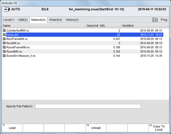
Press H. Browse for Folder dialog box pops up:
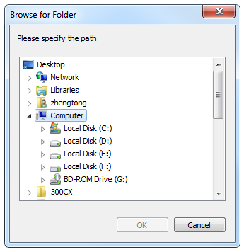
Select Network → target PC, find the desired shared folder, and click OK. File list in the shared folder shows in Network interface.
To select the target program file, press ↑ or ↓.
To load the target program file for machining, press F1.
You can also do the following for a shared program file from the internet:
- F5: unload the loaded program file.
- F8: copy the target program file into NK300CX.
Execute Tool Calibration
This operation is used to measure the selected tool, so as to ensure it works normally during machining.
Types of tool calibration includes the following:
- Mobile calibration
- Fixed calibration
- First-time calibration or calibration after tool changed: default setting
This operation mainly focuses on the last two types of tool calibration.
To set the type of tool calibration, press ![]() → 1 → F8, input the manufacturer password, and modify the value of parameter Calibration Type.
→ 1 → F8, input the manufacturer password, and modify the value of parameter Calibration Type.
Execute Fixed Calibration
This operation is used to measure the tool on a certain fixed position of the machine tool to reconfirm tool offset. It helps to avoid tool length and the clamping position vary during calibration due to tool damage or other causes.
It is mainly used for multi-tool mode and mainly used in the machine tool with tool magazine.
Before executing fixed calibration, do the following:
Ensure parameter N75006 Calibration Type is set to 1.
Modify the value of parameter N75210 Fixed Presetter Position according to the actual situation.
To execute fixed calibration, do the following:
To enter into Coor interface, in Auto / JOG / Handle / Step mode, press
 → 1.
→ 1.Press F5. Fixed Calibrate (Measure Tool Length) dialog box pops up:
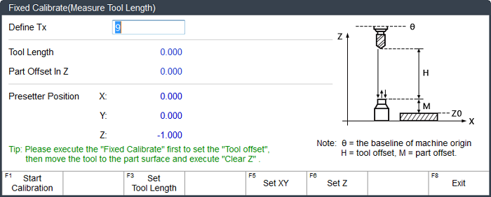
To select the target tool, input the target tool number in Define Tx input box.
To start fixed calibration, press F1.
Note: When the target tool number is different from that of current tool number, the system will automatically change the tool before fixed tool calibration.
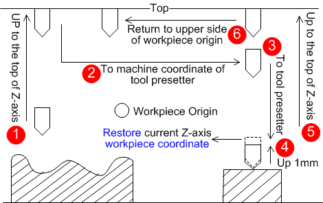
The system starts fixed calibration as follows, and saves the calibration result into the tool length:
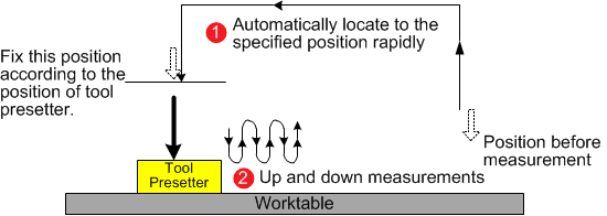
After fixed calibration, move the tool to the surface of the workpiece and do clearing.
See Do Clearing for details.
Execute First-time Calibration or Calibration after Tool Changed
This operation is used to compensate the calibration results to the workpiece offset.
Before executing first-time / calibration after tool changed, do the following:
Ensure parameter N75006 Calibration Type is set to 2.
To define Z-axis workpiece origin, manually move Z-axis to the workpiece surface, and do clearing.
See Do Clearing for details.
To execute first / exchanged calibration, do the following:
To enter into Coor interface, in Auto / JOG / Handle / Step mode, press
 → 1.
→ 1.Press F5. First-time Calibrate / Calibrate after Tool Changed dialog box pops up:
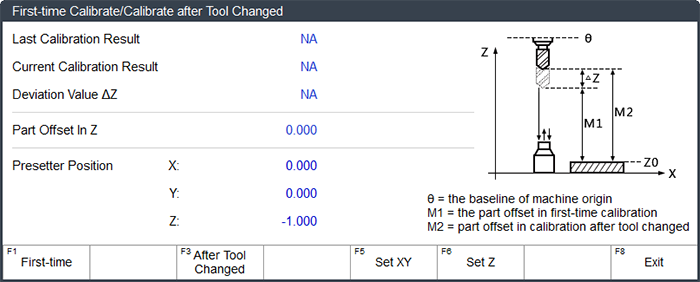
Do one of the following according to the actual situation:
- If it is the first time to execute calibration, pressF1. The system starts to execute first calibration and automatically records current Z-axis machine coordinate.
- After tool change or tool break, press F2. The system starts to execute calibration after tool changed and automatically recovers Z-axis workpiece coordinate of the current point.
Note: Calibration after tool changed must be executed after completion of first-time calibration.
The system automatically records the calibration results into the tool offset:
First-time calibration
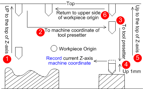
Calibration after tool changed
Adjust the WCS
In programming, programmers select a certain given point on workpiece as origin (also called program origin) to establish a new coordinate system (i.e. workpiece coordinate system (WCS)). This operation is used to adjust the WCS.
To adjust the WCS, do the following:
To enter into Coor Manager interface, in Auto mode, press
 → 1:
→ 1: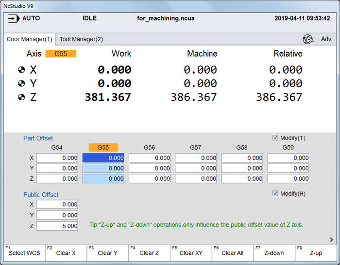
Optional: Select a WCS.
Parameter N62023 Ignore Coordinate System Instruction (G code files) or N65212 Ignore Coordinate System Instruction (ENG files) decides whether the system automatically reads the WCS command in G code / ENG files:
- When it is set to Yes, this step is required, because the system ignores the WCS commands in G code / ENG files.
- When it is set to No (default setting), you can skip the step, because the system automatically reads the WCS command in G code / ENG files.
Select a WCS
This operation is used to select a WCS from G54 to G59 for machining.
Before selecting a WCS, press ![]() → 1 → F2, and modify the value of parameter N62023 Ignore Coordinate System Instruction to Yes.
→ 1 → F2, and modify the value of parameter N62023 Ignore Coordinate System Instruction to Yes.
To select a WCS, do the following:
To move the curser to the target coordinate column, press ← or →.
The color of the column turns into light blue.
To select the coordinate system, press F1.
The name of the selected WCS GXX is highlighted in Part Offset area, and shows in the coordinate display areas on the Coor interface under Gen. functional area and Coor Manager interface under Adv. interface.
Set the Offsets
This operation is used to set the workpiece offset and the public offset. The former is used to show the distance of the workpiece origin relative to the machine origin, while the latter is used to adjust the workpiece origin of each axis for all WCSs.
To set the offsets, do the following:
Set the workpiece offset:
To enable Modify, press T, and input the manufacturer password.
Press ↑, ↓, ← or → to select the target input box, press Enter, and input the modified value.
Set the public offset:
To enable Modify, press H, and input the manufacturer password.
Press ↑, ↓, ← or → to select the target input box, press Enter, and input the modified value.
Optional: To deepen (reduce) or lift (increase) Z-axis public offset, press F7 or F8, and input the adjusted value.
The adjusted value is an accumulated value and it does not differentiate positive value and negative value.
After setting, press T and H to disable modifying the workpiece offset and public offset.
Define the Workpiece Origin
Based on a certain point on the workpiece, this operation is used to define the workpiece origin, which is fixed relative to the certain point and mobile relative to the machine origin.
The selection of origin of WCS should meet the conditions of simple programming, simple dimensional conversion, and small machining error, etc.
To define the workpiece origin, do the following:
To enter into Coor interface, in JOG/Handle/Step mode, press
 → 1:
→ 1:
Do one of the following:
- Do clearing.
- Do centering: it is suggested to do it in Handle mode.
Do Clearing
This operation is used to clear current workpiece coordinate of each axis and set the machine coordinate of each axis to the workpiece offset.
To do clearing, do the following:
Move the machine tool to the position where is the target workpiece origin.
Press F1, and select the target axis to do clearing:
- F1: clear the workpiece coordinate of X-axis.
- F2: clear the workpiece coordinate of Y-axis.
- F3: clear the workpiece coordinate of Z-axis.
- F6: clear the workpiece coordinate of X-axis and Y-axis.
- F8: clear the workpiece coordinate of all axes.
After doing clearing, the workpiece origin turns to zero.
Do Centering
This operation is used to set the workpiece origin for regular-shaped workpieces when the workpiece origin can not be confirmed directly, but you have already known that its position is at the center of two points or a circle.
It can be divided into the following according to the workpiece shape:
- Line centering: used to find the center point by two points on regular rectangular workpieces.
- Circle centering: used to find the center point by three points on circular workpieces.
The other axes should remain static during doing centering on an axis.
Taking X-axis as an example, to do centering, do the following:
Press F2. Line Centering dialog box pops up:

To select the target WCS, press
 .
.Optional: To enable edge finder for accurate centering, press F6:
Enable: Spindle Speed during Centering is valid. Proceed to step 4.
Disable: Spindle Speed during Centering is invalid. Proceed to step 5.
Under this condition, the spindle speed is the value set in the software or program file when
 or
or  is pressed to turn on the spindle.
Optional: Set spindle speed during centering in S in Centering input box.
A large value is not suggested. And it is set to 500 RPM by default.
Move X-axis to one side of the workpiece, and press F1. The system automatically records the machine coordinate of the current point.
Move X-axis to the other side of the workpiece, and press F2. The system automatically calculates the midpoint coordinate based on the coordinate of the current point and records in the last step, and sets it as the workpiece origin.
Select Tools for Machining
This operation is used to select the target tools to machine the target parts of the workpiece when several tools exist in the program file and each tool is used to machine different part.
It is only effective to G code and ENG files.
Before selecting tools for machining, do the following:
Press
 → 1 → F2, ang check related program parameters.
Optional: To enable modifying tool number in ENG files, modify the values of the following parameters to Yes:
- Parameter N65207 Modify Tool No. in ENG File
- Parameter N65208 Auto Modify Tool No.
It is only available to ENG files with 5.50 to 5.53 version.
To enable tool selection, modify the value of one of the following parameters to Yes according to the type of loaded program file:
- Parameter N62022 Enable Tool Selection for G Code File
- Parameter N65203 Enable Tool Selection for ENG File
To select tools for machining, do the following:
Load a G code or an ENG program file containing several tools:
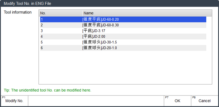
After loading an ENG file with 5.50 to 5.53 version, Modify Tool No. in ENG File dialog box pops up:
Proceed to Step 2.
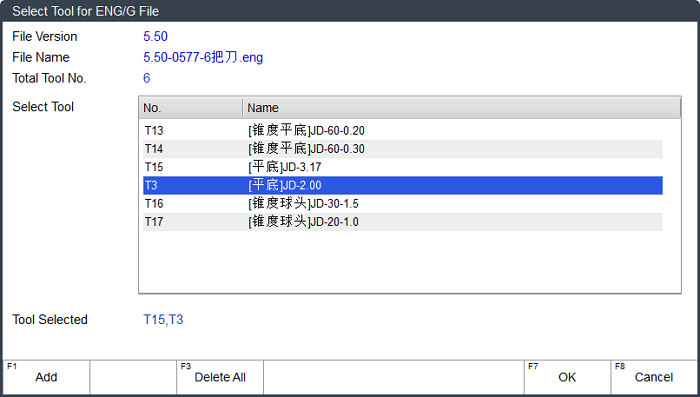
After loading a G code file or an ENG with other versions, Select Tool for ENG/G File dialog box pops up:
Proceed to Step 3.
See Load a Program File for how to load a program file.
Optional: Modify unrecognized tool numbers in the ENG file:
Press ↑ or ↓ to select the target tool, and press F1.
Input the target tool number, press F7 to confirm the setting and return to Modify Tool No. in ENG File dialog box.
To exit from the dialog box, press F7. Select Tool for ENG/G File dialog box pops up.
To add the target tools for machining, press ↑ / ↓ → F1 repeatedly until all target tools are added.
If the same tool appears several times in different lines of the program file, e.g. T1, the system automatically sorts it according to its order in the program file, e.g. T1-1, T1-2, T1-3...You can select the target sorting to machine desired parts.
It is default to select all tools if no tools is added.
Note: If the version of the loaded ENG file is less than 5.50, each time you can only select one tool for machining.
To save the setting, press F7.
After selecting the tools, if you need to select a tool again, press ![]() → 1 → F4 in Auto mode to enter into Select Tool for ENG/G File dialog box, and select the target tool.
→ 1 → F4 in Auto mode to enter into Select Tool for ENG/G File dialog box, and select the target tool.
Execute Selective Machining
This operation is used for an optional skip of the program file, by customizing the start line and end line line of the program block, so that you can freely select the machining range.
To execute selective machining, do the following:
To enter into Coor interface, in Auto mode, press
 → 1.
→ 1.Press F3. Line Selection dialog box pops up:
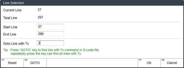
- Current line: show the line number of the current command.
- Total line: show the total line of the loaded program line.
To specify the start line for machining, do one of the following:
Input a line number in the Start Line input box.
Valid range: [Current line, End line]
Specify the tool number in Goto Line with Tx input box, press F2 and start searching. The system automatically locates to the line where the tool number appears, and uses it as the start line.
Pressing F2 several times can locates to the different lines where the tool number appears.
It is only effective to G code files.
To specify the end line for machining, input a line number in the End Line input box.
Valid range: [Start line, Total line]。
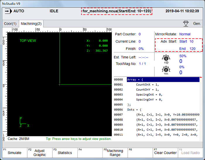
After setting, you can check the start line and end line of the loaded program file at the top of each interface and in Machining interface under ![]() functional area:
functional area:
Execute Machining
This operation is used to run the program form the beginning to the end until the end of block or any intentional interruption.
In AUTO mode, press ![]() .
.
The system automatically starts machining.
During machining, you can do one of the following to control machining:
To stop machining, press
 .
.To pause machining, press
 .
.To resume machining from the exact interrupted position when power interruption or E-stop occurs and the workpiece origin is secured, press
 .
.