System Overview
NK530M Integrated CNC System (Hereinafter referred to as NK530M consists of hardware and software.
Hardware
Lambda terminal board
NK530M supports the following terminal boards:
- Lambda 5S: analog·pulse type. It supports five axes at most.
- Lambda 5E: analog·pulse type. It supports five axes at most.
- Lambda 5M: bus type. It supports 16 axes at most.
- Lambda 21A: analog·pulse type. It supports five axes at most.
- Lambda 21B: bus type. It supports 16 axes at most.
- Lambda 21C: bus type. It supports 16 axes at most.
- Lambda 21E: bus type. It supports 16 axes at most.
DB9M/F cables
See Connection Diagram for how to connect all hardware.
Software
Based on an embedded platform, NK530M software can be divided into the following:
Integral software
- Software with general three axes: the involved axes are X-axis, Y-axis and Z-axis.
- Software with double Y axes: the involved axes are X-axis, Y1-axis, Y2-axis and Z-axis.
- Software with rotary table: the involved axes are X-axis, Y-axis and Z-axis (Y-axis is used as the rotary table).
- Software with four axes (A-type): the involved axes are X-axis, Y-axis, Z-axis and A-axis.
- Software with five axes (AC-type): the involved axes are X-axis, Y-axis, Z-axis, A-axis and C-axis.
- Software with five axes (AB-type): the involved axes are X-axis, Y-axis, Z-axis, A-axis and B-axis (B-axis cannot move with other axes).
Multi-Z axes software
- Linkage configuration
- Alternative configuration
This section takes integral software-software with general three axes as an example. For the introduction for its main software interface, see Main Software Interface.
NK530M Host
The section introduces the front and rear layout of NK530M host.
Front Layout
The front layout of NK530M is as follows:
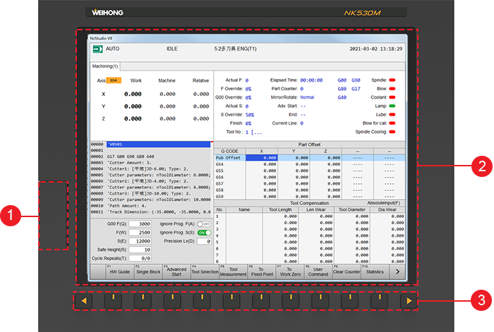
USB interface
Protected by a cover, it is used to connect with a mouse, keyboard, and USB flash disk.
User interface
Human-machine interface, or user’s interface. It is user-friendly and ease of use.
See Main Software Interface for details.
Operation keys
These keys are used to activate the functions indicated by the soft keys, and turn to previous page or next page, including F1 ~ F10 keys, page up key and page down key.
Rear Layout
The rear layout of NK530M host is as follows:
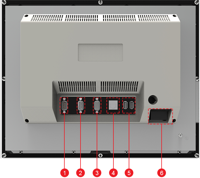
Interface of DB9M/F cable
It is used to connect with the keypad panel.
Interface of Lambda terminal board
It is used to connect with Lambda terminal board.
VGA interface
It is used to connect with VGA devices.
LAN interface
It is used to connect with network, with 100Mbps transmission rate.
USB interface
It is used to connect with a mouse, keyboard, and USB flash disk. There are two USB interfaces.
Power supply interface
It is used to connect with 24V power supply.
WH301 Keypad Panel
The section introduces the front and rear layout of WH301 keypad panel.
Front Layout
The front layout of WH301 keypad panel is as follows:

Keys for system operation
 : reset the system.
 : switch to NcGateway page.
 : switch to MACH page.
 : switch to TRACE page.
 : switch to PROG page.
 : switch to SYSTEM page.
 : switch to PARAM page.
Keys for editing
 /
/  : delete text.
 : insert text.
 /
/  : turn to the previous or next page.
 : turn to the first page.
 : turn to the last page or the last line of text.
 /
/  /
/  /
/  : move up / down / left / right the cursor.
 : select functions.
Numeric keys
Alphabet keys
Rear Layout
The rear layout of WH301 keypad panel is as follows:
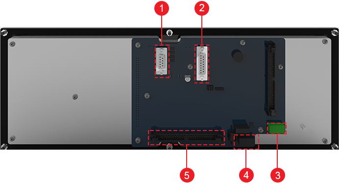
Interface of DB9M/F cable
It is used to connect with NK530M host.
Handwheel interface
It is used to connect with a handwheel.
Interface of E-stop signal
It is used to connect with E-stop signal interface of WH308M operation panel.
Power supply interface
It is used to connect with 24V power supply.
50P interface
It is used to connect with 50P interface of WH308M operation panel.
WH308M Operation Panel
The section introduces the front and rear layout of WH308M operation panel.
Front Layout
The front layout of WH308M keypad panel is as follows:
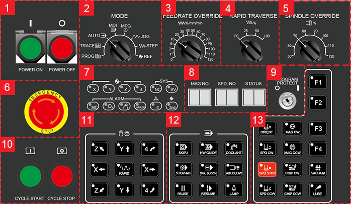
Power switches
It is used to control the system power.
Mode selection knob
It is used to select a machining mode, including AUTO, HW, JOG, INC, and REF, and switch to related pages, including Program, Trace, and MDI.
Feed override knob
It is used to adjust feed override from 0% to 120%.
Rapid feed override knob
It is used to adjust G00 override from 0% to 100%.
Spindle speed override knob
It is used to adjust spindle speed override from 50% to 120%.
E-stop switch
It is used to stop the movement of the machine tool when the machine tool is in danger, so as to protect the operator and machine tool.
After danger is cleared, you can rotate the switch clockwise to remove the E-stop alarm.
Indicator lamp
Reference indicator lamp: the related lamp is on when the corresponding axis returns to the machine origin.
System indicator lamp: the related lamp is on when failure of Lambda terminal board and servo alarms occur.
Exception indicator lamp: the related lamp is on when an exception in the machine tool, tool magazine, lube and air pressure occurs.
Fixture indicator lamp: the lamp is on when the fixture is clamped.
Indicator lamp for the 2nd reference point: the lamp is on when Z-axis returns to the second reference point.
LED display
It is used to show the number of tool magazine and the current tool number.
Program lock
It is used to turn on / off program editing.
Program start / stop key
It is used to start / stop machining.
Keys for axis direction
These keys are used to move the target axis to the target position. In Manual mode:
Press an axis direction key and Rapid key. The machine tool moves at rapid jog speed.
Press an axis direction key. The machine tool moves at jog speed.
Keys for common operations
Keys for machining: including SKIP(), STOP-M0, PAUSE, HW GUIDE, SGL BLOCK and RUSUME.
Keys for turning on/off common ports: including COOLANT, AIR BLOW, and LAMP.
Keys for auxiliary operations
Keys for spindle control
They are used to control the movement of the spindle, including ORIENT, SPD CW, SPD STOP and SPD CCW.
Keys for tool magazine control
They are used to control the movement of the tool magazine, including MAG CW and MAG CCW.
Keys for chip evacuation
They are used to evacuate chip, including CHIP CW and CHIP CCW.
Extended keys
They are used to customize functions, including F1, F2, F3 and F4.
Keys for vacuum absorbing
They are used to turn on / off vacuum absorbing.
Lube key
It is used to turn on / off lube.
Rear Layout
The rear layout of WH308M operation panel is as follows:
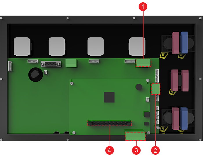
Power switch
It is used to connect with the power switch of the machine tool.
See Wiring Diagram of the Electrical Switch for details.
Interface of E-stop signal
It is used to connect with E-stop signal interface of WH301 keypad panel.
Power supply interface
It is used to connect with 24V power supply.
50P interface
It is used to connect with 50P interface of WH301 keypad panel.
Main Software Interface
The main interactive user interface of NK530M is as follows:
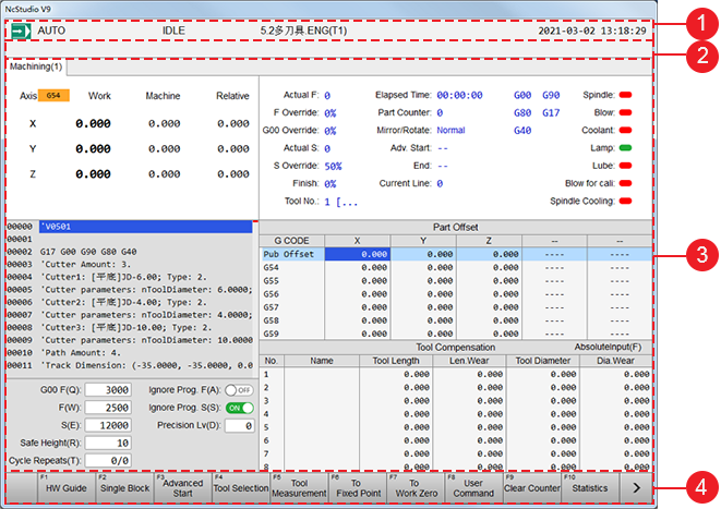
Status bar
You can check the following information in this bar:
- Current mode, including REF, JOG and AUTO.
- Current status, including AUTO and RUN.
- Name of the current program file.
- Machining time.
Information bar
It shows information, including machining process, alarms, etc.
Functional page
It shows child pages corresponding to each main functional keys.
Functional keys
It shows commands corresponding to F1 ~ F10 operation keys.
Their meanings differ with the child pages.