Wiring
This section introduces the connection diagram of each hardware of NK530M, supported signal type and interface of Lambda terminal board.
Diagrams
This section introduces the dimensional drawing, connection diagram and wiring diagram of electrical switch.
Dimensional Drawing (Unit: mm)
The dimensional drawing is as follows:

Connection Diagram
NK530M includes bus control system and analog·pulse control system. Connection diagram of these two control system are almost the same.
This section takes the connection diagram of the bus control system as an example:

Wiring Diagram of the Electrical Switch
This wiring diagram describes the connection between the power switch interface of WH310 keypad panel and the power switch of the machine tool.
The wiring diagram of the electrical switch is as follows:

Signal Types
The supported signal types are as follows:
Binary Input Signal
The connection of binary input and mechanical switch is as follows:

Binary input signal is active in low/high voltage:
- Conducting to COM in NO connection means signal detected.
- Disconnecting with COM in NC connection means signal detected.
NK530M system supports inputs active in high/low voltage:
- When the common port S on the Lambda terminal board is connected to COM, inputs are active in high voltage.
- When the common port S on the Lambda terminal board is connected to +24V, inputs are active in low voltage.
Relay Output Signal
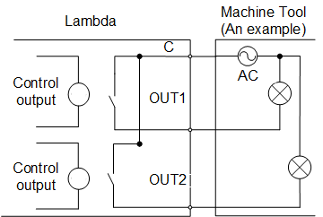
The outputs on the Lambda terminal board are relay outputs.
The load capacity of relay output contact points is AC 250V/5A, used to control 220V AC load of low power. If high power load is needed, a contactor should be connected as follows:
Analog Output Signal
AVC port, externally connected with the inverter analog voltage frequency command input port, can output controllable voltage from 0V to 10V.
AVC port can control inverter frequency by voltage change in order to master spindle speed.

Differential Output Signal
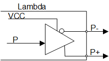
Pulse command format of control driver motion is pulse + direction, negative logic. The maximum pulse frequency is 1MHz.
Note: Bus control system does not support this signal type.
The pulse command output mode is as follows:

The differential signal output mode is as follows:
Interface Definitions
This section takes the interface definitions of Lambda 21B as an example.
Interface of Lambda 21B includes the following:
Handwheel Interface
The definition of handwheel interface is as follows:
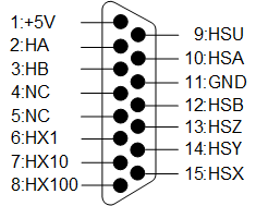
+5V: Power on the handwheel
+5V: Encoder phase A signal
HB: Encoder phase B signal
NC: No signal
HX1: Selection of X1 override
HX10: Selection of X10 override
HX100: Selection of X100 override
HSU: Selection of the 4th axis
HSA: Selection of the 5th axis
GND: Digital ground
HSB: Selection of the 6th axis
HSZ: Selection of Z-axis
HSY: Selection of Y-axis
HSX: Selection of X-axis
Pulse Axis Interface
The definition of pulse axis interface is as follows:
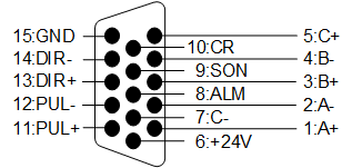
A+/A-/B+/B-/C+/C-: Feedback signal of encoder phase A / B / C. Input, differential signal transmission mode. Receive the differential output from encoder signal (phase A, B, C) of drive frequency divider (equaling to RS422).
ALM: Driver alarm signal. Input. When breakdown occurs in the servo drive, the output (transistor) will be closed or disconnected.
SON: Servo ON signal. Output. Used for opening (power on) and closing (power off) the servo motor. When this signal is connected to COM-, dynamic brake will be released and thus the servo drive is allowed to work (servo enabled).
CLR: Signal of clearing drive alarms. Output. Clear alarms of servo drives. Only alarms with removable attributes can be cleared.
PUL+/PUL-: Pulse output. Output, differential signal transmission mode.
DIR+/DIR-: Direction output. Output, differential signal transmission mode.
+24 V and GND: DC24V power supply. Output. Connected to the servo drive.
MECHARTROLINK-II Interface
The definition of MECHARTROLINK-II interface is as follows:
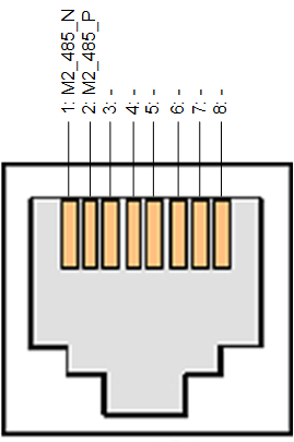
M2_485_N: Negative differential signal of MECHARTROLINK-II (Yaskawa-bus type).
M2_485_P: Positive differential signal of MECHARTROLINK-II (Yaskawa-bus type).
-: No signal.
GNDP: RJ45 shield shell connects to the ground.