Set Workpiece Origin
A certain point on the workpiece is selected as the workpiece origin (origin of the axis coordinate system of the machining paths). The workpiece origin is fixed relative to the points on the workpiece and mobile relative to the mechanical origin. Programmers select the workpiece origin commonly under considerations of convenience for programming and size conversion, and less machining error.
You can select one from the following methods to set the position of the workpiece origin:
Clearing
Centering
Setting workpiece offset and public offset parameters
Tool calibration
Setting tool compensation parameters
Clearing
When the machining accuracy requirement is not very high and the work piece has an irregular shape, you can select the workpiece origin with the clearing method. Clearing means to set the workpiece coordinates of the current point to 0.
Taking the X axis as an example, follow the steps below to execute clearing:
Control the X axis to move to the target point which you want to set as the workpiece origin.
In Auto mode, click the F3 pull-down menu in the operation button bar and select XClear; or press the F3 key; or click the X-axis workpiece coordinate button in the axis coordinate area, a message box will be displayed, as shown below:

Click Yes. The X-axis workpiece coordinate of the current point becomes 0.
Centering
Two types of centering are supported: line centering and circle centering. Line centering is mostly used to locate the center of regular rectangle work pieces while circle centering circular work pieces.
Taking line centering for the X axis as an example, follow the steps below:
In Manual mode, go to Machine > Centering in the menu bar to open the Center window:
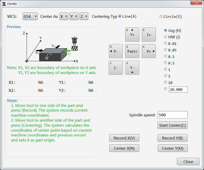
Optional: To change the workpiece coordinate system, click the WCS pull-down menu. Workpiece coordinate systems of G54–G59 are supported. The default workpiece coordinate system is G54.
Set Centering Type to Line.
Optional: If an edge finder is used for more accurate positioning, follow the steps below:
a. In the Spindle speed field, enter the target spindle speed during centering. Its value should not be too large and is set to 500 (r/min) by default.
b. Click Start Center to make it highlighted in green.
Click the X+ / X- button to make the X axis move to one end of the work piece. Click Record X to record the X-axis mechanical coordinate of the current point into the system.
Click the X+ / X- button to make the X axis move to the other end of the work piece. Click Center X. The system automatically calculates the X-axis midpoint mechanical coordinate based on the X-axis mechanical coordinate of the current point and the X-axis mechanical coordinate recorded in the last step, and sets the X-axis workpiece coordinate of the midpoint to zero.
Setting Workpiece Offset and Public Offset
Workpiece offset indicates deviation of the workpiece origin from the mechanical origin. Public offset indicates deviation of a whole workpiece coordinate system from the positions established based on the workpiece offset.
Follow the steps below to set the workpiece offset and public offset parameters:
Click the Offset tab in the function window.
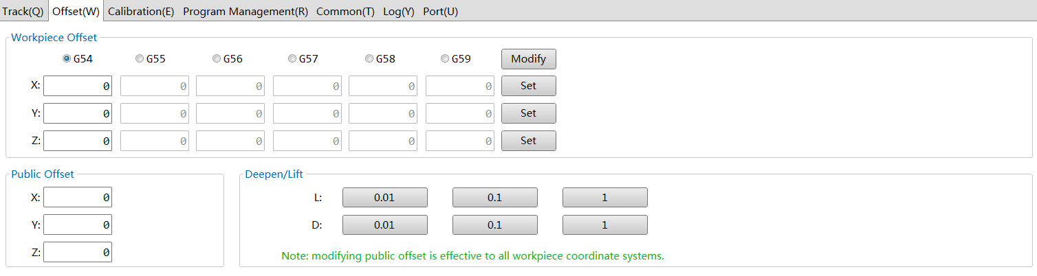
Select the target workpiece coordinate system, such as G54.
Enter X/Y/Z-axis workpiece offset in the X/Y/Z fields.
Click the Set buttons behind the X/Y/Z fields. In the popped up dialog box, click Yes to set the X/Y/Z-axis workpiece coordinate of the current point to 0.
Optional: Enter X/Y/Z-axis public offset values in the X/Y/Z fields in the Public Offset area.
Optional: Click the 0.01/0.1/1 buttons in the Deepen/Lift area to adjust the Z-axis public offset by certain amount separately.
Tool Calibration
Tool calibration is used to measure the selected tool and check the tool offset to ensure that the tool can work properly.
Follow the steps below to calibrate the selected tool:
In Auto or Manual mode, click the Calibration tab in the function window.
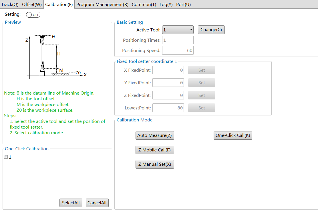
Set Setting in the upper left corner to ON.
In the Basic Setting area, click the Active Tool pull-down menu, select the target tool number, and set the following parameters:
Positioning Times: Indicates the times of fine positioning when approaching the tool sensor during tool calibration.
Positioning Speed: Indicates the speed when approaching the tool sensor during tool calibration.
In the Fixed tool setter coordinate 1 area, set the parameters of the fixed tool sensor:
X FixedPoint: X-axis mechanical coordinate of the fixed tool sensor
Y FixedPoint: Y-axis mechanical coordinate of the fixed tool sensor
Z FixedPoint: Z-axis mechanical coordinate of the fixed tool sensor
LowestPoint: Mechanical coordinate of the Z-axis lowest point during tool calibration.
Select one from the following tool calibration methods:
- Fixed calibration
- First-time calibration/Calibration after tool change
- Mobile calibration
Fixed Calibration
If a tool is replaced due to being broke or other reasons, the length of the new tool and where the new tool is clamped may be different from the replaced one. In this case, fixed calibration can be used to measure the length of the new tool from a fixed position of the machine and determine the tool offset for better machining accuracy. Fixed calibration is applicable to machine with a tool magazine.
Before executing fixed calibration, set the manufacturer parameter Tool Calibration Type to 1.
Follow the steps below to execute fixed calibration:
In the Calibration Mode area of the Calibration tab, select one method:
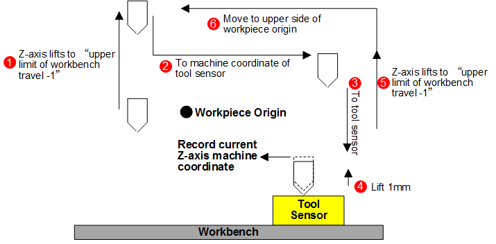
Automatic measuring: Click Auto Measure. The system carries out fixed calibration automatically.
The process of automatic fixed calibration is shown below:

Manual calibration: Control the tool to move to the tool sensor surface and click Z Manual Set. The system records the calibration result into the tool offset.
After fixed calibration is finished, control the tool to move to the work piece surface and execute Z-axis clearing.
First-time Calibration/Calibration After Tool Change
First-time calibration/Calibration after tool change operations are used to record tool differences into the workpiece offset.
The operations are applicable to machine without automatic tool change functions and need to be executed every time a tool is changed.
Before executing first-time calibration/calibration after tool change operations:
Set the manufacturer parameter Tool Calibration Type to 2.
Control the Z axis to move to the work piece surface and execute clearing to determine the workpiece origin.
In the Calibration Mode area of the Calibration tab, select one method:
First-time calibration: Click First Cali. The system automatically records the Z-axis mechanical coordinate of the current point.
Calibration after tool change: Click Second Cali. The system automatically recovers the Z-axis workpiece coordinate of the current point.
First-time calibration process and calibration after tool change process are similar, as shown below:
Mobile Calibration
During mobile calibration, the Z-axis workpiece coordinate is automatically cleared. Only workpiece offset of the current workpiece coordinate system will be changed.
Before executing mobile calibration, ensure that:
- Set the manufacturer parameter Tool Calibration Type to 1.
In the Calibration Mode area of the Calibration tab, Click Z Mobile Cali. The system executes tool calibration at the current position and records the calibration result into the tool offset parameter.
Setting Tool Compensation Parameters
For details, see Tool Compensation Parameters.